
Supply-voltage-splitter
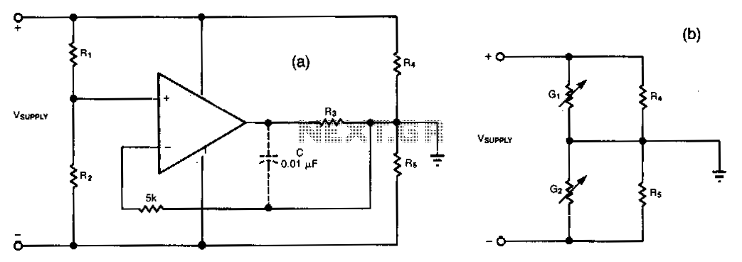
This simple circuit can convert a single supply voltage, such as a battery, into a bipolar supply. Sense resistors R1 and R2 establish relative magnitudes for the resulting positive and negative voltages. Their rail-to-rail value equals V_SUPPLY. Resistors R4 and R5 represent the load impedances. For example, equal-value sense resistors produce 1/2 V_SUPPLY across each of the load resistors, R4 and R5. The operational amplifier maintains these equal voltages by sinking or sourcing current through R3; the op amp's action is equivalent to that of variable conductances G1 and G2 in shunt with each load resistor. A value for R3 should be chosen such that the largest voltage across it, representing the greatest load-current mismatch, does not exceed the op amp's output voltage capability for the application. A buffer amplifier can be added at the op amp's output to provide greater load currents. If bypass capacitors across the load resistors are needed, connect a capacitor to ensure that the amplifier remains stable.
The circuit described utilizes an operational amplifier (op amp) to create a bipolar supply from a single voltage source, such as a battery. The configuration relies on the use of sense resistors R1 and R2, which are critical in determining the output voltages. When equal values are selected for R1 and R2, the output voltages across the load resistors R4 and R5 are symmetrically distributed, each receiving half of the input voltage (V_SUPPLY/2).
The operational amplifier is central to the feedback mechanism that regulates the output voltages. By adjusting the current flow through R3, the op amp maintains the balance of the voltages across the load resistors. This feedback loop effectively simulates variable conductances G1 and G2, which act in parallel with R4 and R5, respectively. This configuration allows for dynamic adjustment based on load conditions, ensuring that the output remains stable even as load demands change.
When selecting the resistor R3, it is essential to consider the maximum voltage that will appear across it, which corresponds to the potential mismatch in load currents. This selection must be made carefully to ensure that the op amp does not exceed its output voltage limits, which could lead to distortion or failure in the circuit operation.
For applications requiring higher load currents, a buffer amplifier can be integrated at the output of the op amp. This buffer serves to isolate the op amp from the load, allowing it to operate within its optimal range while delivering the necessary current to the load.
Additionally, the inclusion of bypass capacitors across the load resistors R4 and R5 can enhance circuit stability by filtering out high-frequency noise and providing a reservoir of charge to the load during transient conditions. These capacitors should be connected as indicated in the schematic to ensure that they effectively stabilize the output voltage levels and improve the overall performance of the circuit.This simple circuit can convert a single supply voltage, such as a battery, into a bipolar supply. Sense resistors Rl and R2 establish relative magnitudes for the resulting positive and negative voltages. Their rail-to-rail value, of course, equals VsUPPLY· R4 and R5 represent the load impedances. For example, equalvalue sense resistors produce 1/z VsvPPLY across each of the load resistors, R4 and R5.
The op amp maintains these equal voltages by sinking or sourcing current through R3; the op amp"s action is equivalent to that of variable conductances Gland G2 in shunt with each load resistor. Choose a value for R3 so that the largest voltage across it, the greatest load-current mismatch, won"t exceed the op amp"s output-voltage capability for the application.
You can add a buffer amplifier at the op amp"soutput to provide greater load currents. Ifyou need bypass capacitors across the load resistors as well, connect a capacitor (dashed lines) to ensure that the amplifier remains stable. 🔗 External reference