
Surround Sound Decoder circuit diagram
Parts List:
- R1, R2, R7, R8, R12, R13, R18, R19, R20 = 47kΩ
- R3, R4, R5, R6, R21, R22, R34, R35 = 10kΩ
- R9, R10, R11, R14, R15, R16, R17 = 15kΩ
- R23, R24, R25, R33, R36 = 100Ω
- R26, R27, R28, R31, R32 = 100kΩ
- R29, R30 = 5.6kΩ
- C1, C8 = 47µF 25V
- C2, C7, C9, C14, C23 = 47nF 100V
- C3, C6 = 1µF 100V
- C4, C5, C10 = 33pF 100V
- C11, C12, C15 = 10µF 25V
- C13 = 82nF
- C16 = 18pF 100V
- C17 = 100pF (mini adjustable capacitor)
- C18 = 2.2nF
- C19 = 4.7µF 25V
- C20 = 100nF 100V
- C21 = 10nF
- C22 = 180pF.
This circuit represents a passive surround sound configuration, which does not require active components for operation. It relies solely on a combination of resistors and electrolytic capacitors. Important notes include the recommendation to use full-range speakers, avoiding woofers or tweeters for rear channels, and ensuring the use of 5W resistors rated at 1/4W.
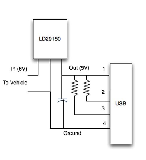
The circuit also encompasses a USB-powered computer speaker design, commonly referred to as multimedia speakers for PCs. This circuit features a single-chip design, operates on low-voltage power supply, and is compatible with USB power from computers. It includes simple heat-sinking, is cost-effective, and offers a wide temperature tolerance. The core of this circuit is the TDA2822M IC.
Additionally, the circuit outlines a simple sound effect generator utilizing the UM3561 sound generator chip. This chip is capable of generating four distinct sound effects. The operational flow involves the UM3561 producing a sound signal, which is then amplified by a 2N3706 transistor, enabling audible output through a speaker.
Furthermore, a stereo digital volume control circuit is presented, designed to enhance manual volume management within a stereo amplifier setup. In this configuration, a push-to-on switch (S1) facilitates the volume increase for both channels, while a corresponding switch (S2) manages volume reduction.
Lastly, a beeper sound circuit diagram is provided, which emulates the sound of a pager. This circuit utilizes a 555 timer oscillator, which operates in a periodic ON and OFF manner to generate a "beep-beep" sound. The first 555 IC in the circuit serves as the primary oscillator.Surround Sound Decoder circuit diagram. The circuit`s operation starts as the stereo sound signal transports surround sound information on the master volume part of the circuit. This will drive the Left channel Lch attached to Model TL072 IC1A and IC1b in which Right channel Rch is attached.
The outputs on these operational amplifiers would serve as the input buffer to the following stages of the circuit. The following diagram is an small surround sound decoder schematics. You may use this decoder surround sound systems for your home audio system. Parts List: R1-2-7-8-12-13-18-19-20=47Kohm R3-4-5-6-21-22-34-35=10Kohm R9-10-11-14-15-16-17=15Kohm R=23-24-25-33-36=100ohm R26-27-28-31-32=100Kohm R29-30=5. 6Kohm C1-8=47uF 25V C2-7-9-14-23=47nF 100V C3-6=1uF 100V C4-5-10=33pF 100V C11-12-15=10uF 25V C13=82nF C16=18pF 100V C17=100pF mini adjustable capacitor C18=2.
2nF C19=4. 7uF 25V C20=100nF 100V C21=10nF C22=180pF. This is the diagram of passive surround circuit. Passive surround doesn`t required any active components to make the circuit works. The circuit just need the combination of resistors and electrolytic capacitors. Notes: Use full range type of speaker. Do not use woofer or tweeter speakers for rear speakers. 5W resistors is a must, 1/4 or. This is the circuit diagram of USB powered computer speaker, or it widely known as multimedia speakers for PCs. The circuit has single-chipbased design, low-voltage electrical power supply, compatibility with USB power from computer, simple heat-sinking, inexpensive, large flexibility and wide temperature tolerance.
At the heart of the circuit is IC TDA2822M. This IC is, . This is a really simple sound effect generator based single sound generator chip UM3561. The UM3561 will generate four kinds of sound effects. The basic operation is that the UM3561 will generate the sound signal, then the signal delivered to 2N3706 (as speaker driver) to be amplified so you can hear the sound from a. Here is the circuit diagram of stereo digital volume control. This circuit could possibly be applied for upgrading your manual volume management within a stereo amplifier circuit.
In this particular circuit, push-to-on switch S1 controls the forward (volume enhance) operation of the two channels while a identical switch S2 controls reverse (volume reduce) operation of. This is the circuit diagram of beeper sound. The circuit will generate the sound of a beeper which similar with the one in pagers. It produces a "beep-beep" sound. The work of this circuit is simple, the circuit applied the 555 timer oscillator which is turned ON and OFF periodically.
The first 555 IC (left. 🔗 External reference
Related Circuits
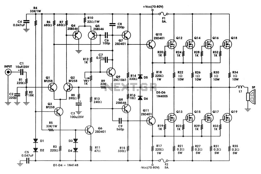
400 W MOSFET Audio Amplifier circuit using IRFP448. This circuit is categorized under amplifiers and includes five circuit diagrams. For more detailed information, refer to the main post titled "400 W MOSFET Audio Amplifier Using IRFP448." This post also...
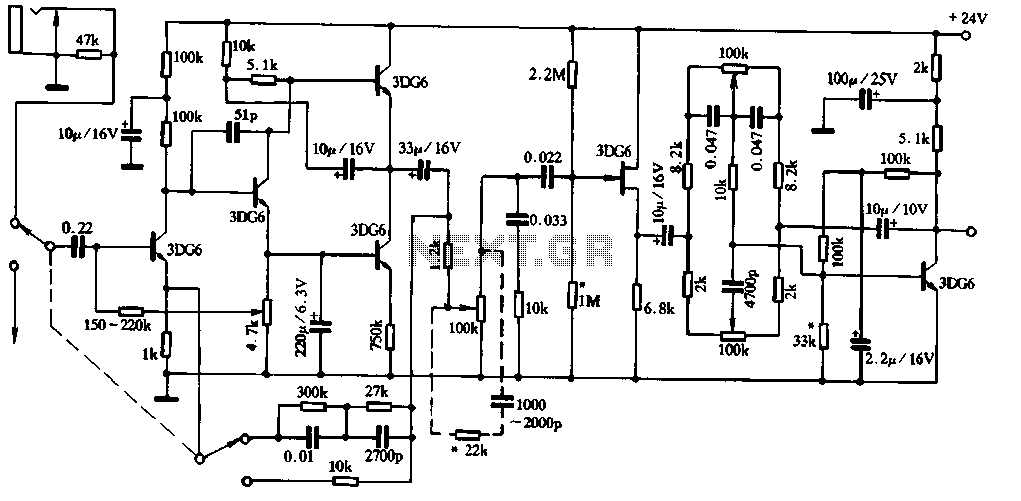
Figure 1-91 illustrates a practical loudness volume control circuit designed for integration with a preamplifier and tone control system. This circuit is positioned behind the output capacitor load (OCL) and can be connected to the main amplifier. Its effectiveness...
How can a 1950 Studebaker be enhanced? By installing an iPod Nano in the dashboard. The team at MAYA Design created a touch-controlled sound system for this project, referred to as the "Nano-Baker" or "Stude-iPod," utilizing a pair of...
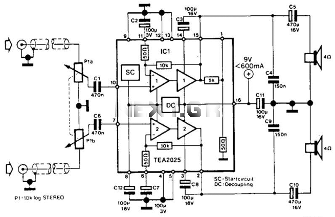
Using a Thomson TEA2025, this stereo amplifier delivers 1 W per channel into a 4-ohm load with a 9-V supply. The input sensitivity is 25 mV peak-to-peak for full output. It is important to ensure that pins 4, 5,...

A simple technique for measuring frequencies across a wide range with acceptable accuracy limits using a PC is presented. This method follows the basic principle of measuring low frequencies, where the period of a complete wave is measured and...
1. Abstract Wet-garden is an interactive flower garden and an ambient indoor sculpture. When people walk around it, it changes motion and LED blinking speed. Wet-design is designed for everyone who wants a tangible interaction object and an interesting...