
Switch-mode Converter Starts With Full Load Connected
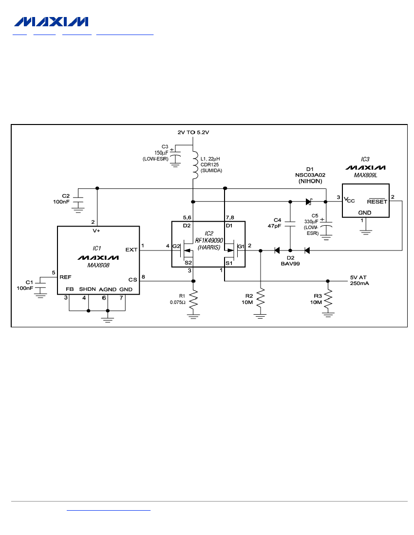
The regulated boost converter is designed to step up the input voltage to a higher output voltage while maintaining a stable output under varying load conditions. The additional circuitry plays a crucial role in managing the load connection during the start-up phase. By disconnecting the load until the output voltage stabilizes, the converter prevents potential damage to the load and ensures that the system operates within safe parameters.
The gate-drive voltage is a critical factor in the performance of the switching MOSFET. A sufficiently high gate-drive voltage is necessary to minimize the on-resistance of the MOSFET, which in turn reduces power losses and improves efficiency. During the start-up phase, the gate-drive voltage is intentionally limited to prevent excessive current draw, which could lead to instability or failure in the converter's operation.
Once the output voltage reaches the desired regulation level, the load is reconnected, allowing the converter to operate under full load conditions. This sequence ensures that the converter can handle the demands placed on it without compromising performance or reliability. The design of the control circuitry must take into account the timing and thresholds for disconnection and reconnection of the load, as well as the characteristics of the MOSFET and other components involved in the boost conversion process.
Overall, the regulated boost converter's design emphasizes safety and efficiency, particularly during the critical start-up phase, ensuring that it can deliver the required output voltage reliably under all operating conditions.To ensure a full-load start-up, the extra circuitry in this regulated boost converter disconnects the load until the output voltage achieves regulation. Proper operation requires a gate-drive voltage sufficient to provide low on-resistance in the switching MOSFET, but at start-up this drive is limited to the
🔗 External reference
Related Circuits
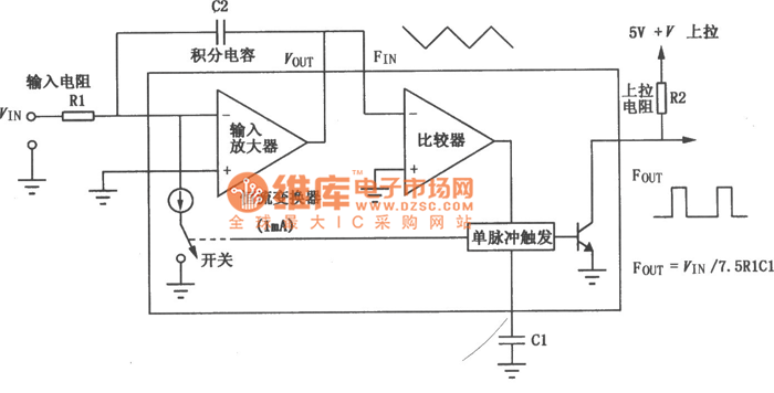
The VFC62 is a voltage-to-frequency and frequency-to-voltage converter that effectively transforms analog signals into digital signals. The digital output is presented in an open collector format, where the digital pulse repetition rate is directly proportional to the amplitude of...
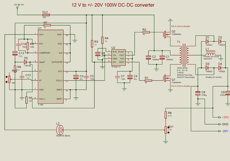
A DC to DC converter circuit is designed to convert a DC voltage to another DC voltage with different levels. This specific converter transforms a +12 V DC input into a symmetrical output of +/-20 V DC. Such circuits...
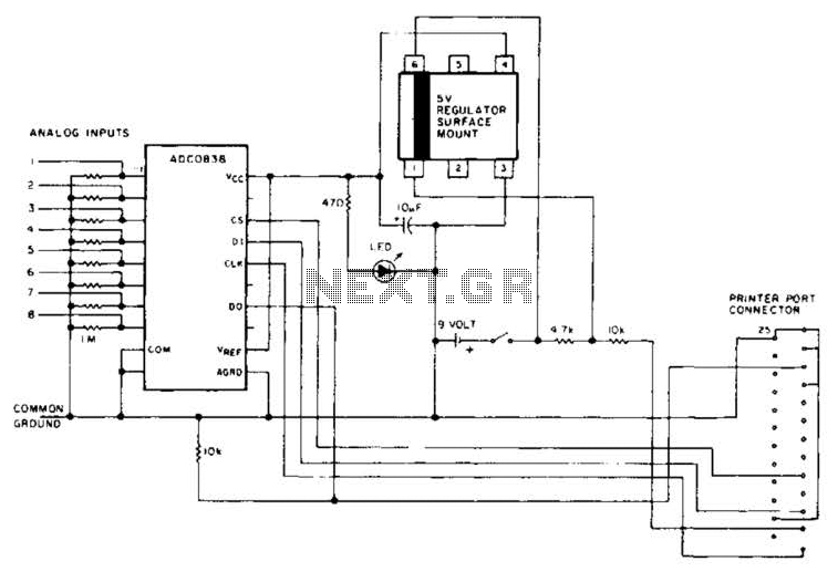
An A/D converter by National Semiconductor (ADC0838) converts 0 to 5 V analog inputs into a digital data format. A 9 V battery is utilized. The converter connects to the pointer port connector through a 25-pin connector. The ADC0838 is...
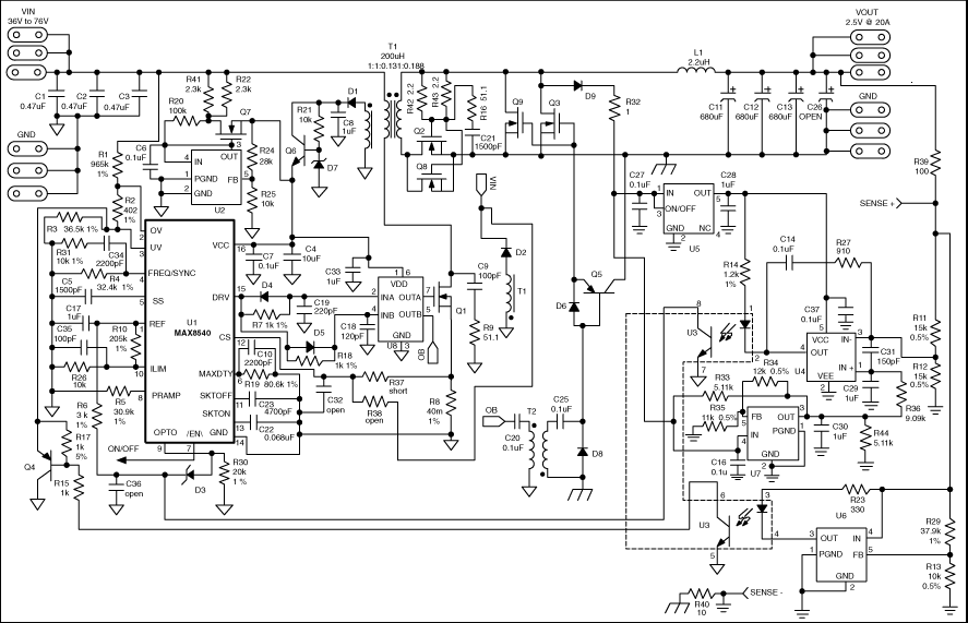
This application note details the design of a 50-watt, isolated, forward converter, utilizing the MAX8540 synchronizable, high-frequency, current-mode PWM controller. The schematic design of the 50-watt isolated forward converter using the MAX8540 involves several key components and stages to ensure...
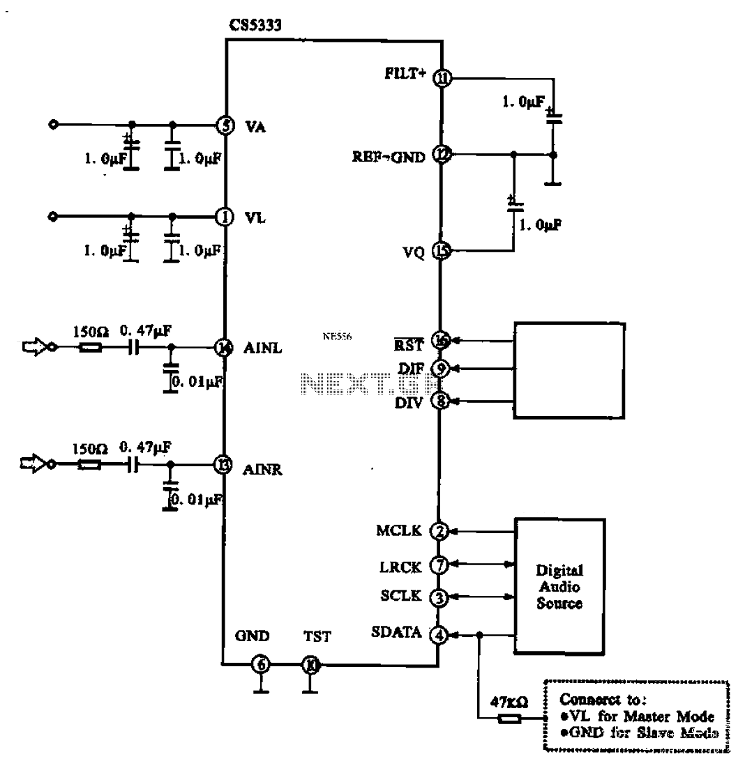
Audio A/D converter circuit configuration using the CS5333 chip, which is a high-performance 24-bit, 96 kHz stereo A/D converter commonly used in digital products. This circuit converts one or more audio signals into a digital signal for processing and...
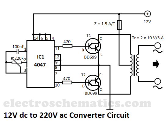
This DIY 12V to 220V voltage converter is built with a CMOS 4047, which serves as the main component of this compact voltage converter that transforms 12V DC into 220V AC. The 4047 functions as an astable multivibrator; at...