
Switchable Vhf Active Antenna Circuit
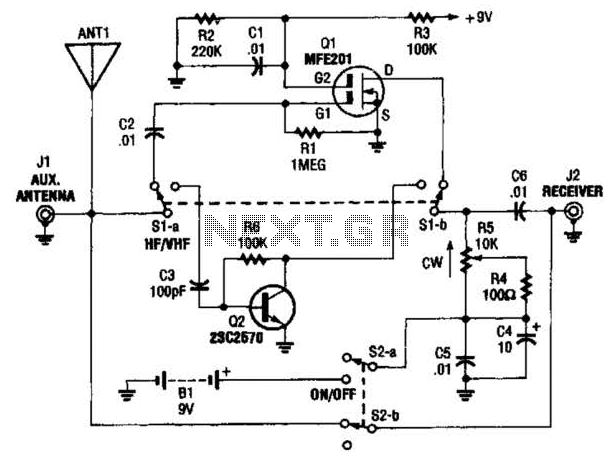
The AA-7 active antenna is designed to enhance the reception of radio frequency signals through the use of two key active components. The MFE201 N-channel dual-gate FET (Q1) serves as the primary amplification element, providing high gain and low noise characteristics essential for effective signal processing. This type of FET is particularly advantageous in RF applications due to its ability to handle high frequencies and its excellent linearity.
The second component, the 2SC2570 silicon transistor (Q2), functions as a secondary amplifier, further boosting the signal after it has been processed by the FET. This transistor operates within the VHF range, making it suitable for a variety of radio applications. The combination of these two components allows for the creation of two independent RF preamplifiers, which can be switched on or off as needed. This switchable feature enables users to optimize signal reception based on specific conditions or requirements.
The design of the AA-7 antenna emphasizes versatility and performance, making it ideal for use in environments where signal strength may vary. By utilizing high-quality components and a thoughtful configuration, the AA-7 aims to provide clear and reliable signal amplification for a range of RF applications. The AA-7 active antenna contains only two active elements: Ql (an MFE201 N-chanriel dual-gate FET) and Q2 (a 2SC2570 ripri VHF silicon transistor), which provide the basis of two independent, switchablc RF preamplifiers. 🔗 External reference
Related Circuits
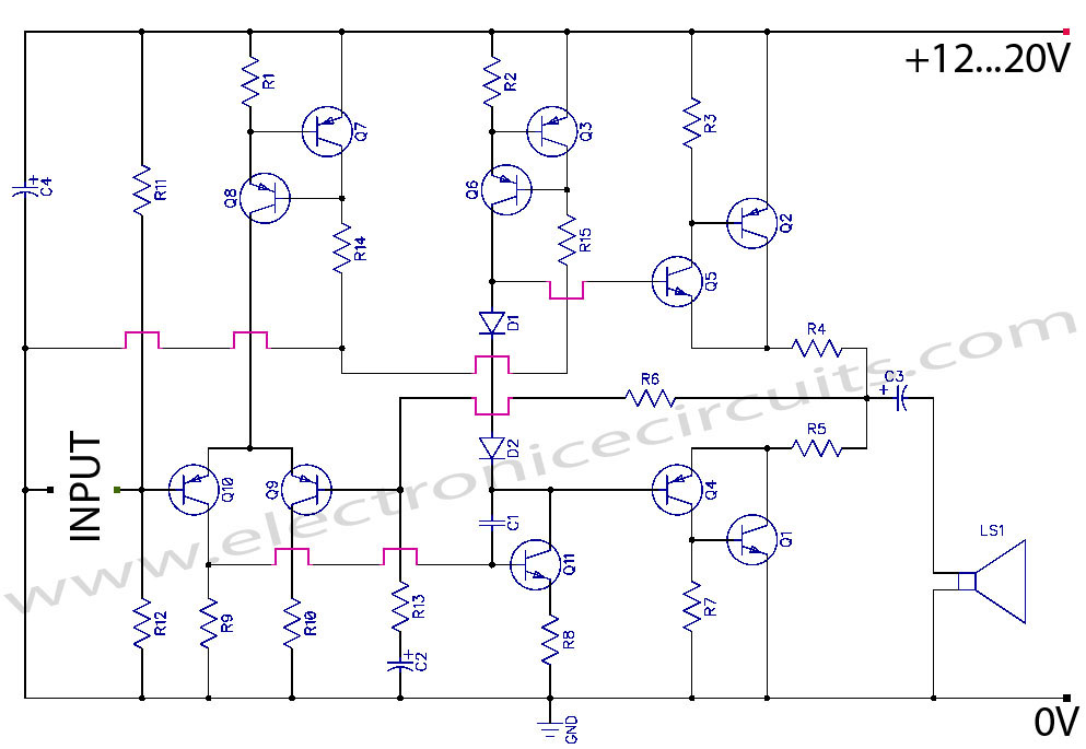
Discrete Class AB Transistor Audio Power Amplifier Circuit Diagram. This is a Class AB transistor power amplifier. It is a simple amplifier to... A Class AB transistor audio power amplifier is designed to provide high-quality amplification for audio signals while...
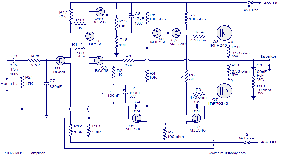
Hi-fi 100W MOSFET power amplifier circuit. Operates from a 45V dual supply. Delivers 100W to an 8-ohm speaker and 160W to a 4-ohm speaker, with low distortion. The Hi-fi 100W MOSFET power amplifier circuit is designed to provide high-quality audio...
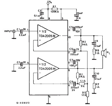
TDA2005 car audio amplifier circuit diagram electronic project using few external electronic parts The TDA2005 is a robust integrated circuit designed for audio amplification in automotive applications. This circuit diagram outlines a project for a car audio amplifier that utilizes...
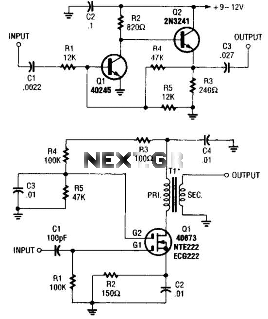
These two buffer/amplifiers have been effectively utilized with variable frequency oscillators (VFOs): one (depicted in A) is constructed using a pair of bipolar NPN transistors, while the other (illustrated in B) is designed around a dual-gate MOSFET. The first buffer/amplifier,...
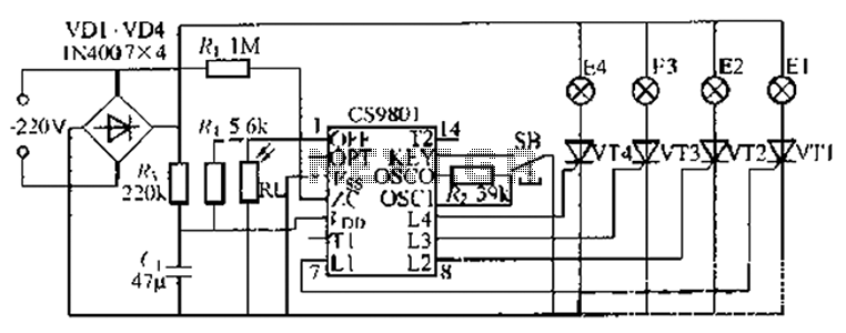
The ASIC is a flashing light string controller featuring four outputs. It includes a single key cycle control with six different lighting effects, and it allows for the selection of either 16 or 8 patterns. The circuit incorporates a...
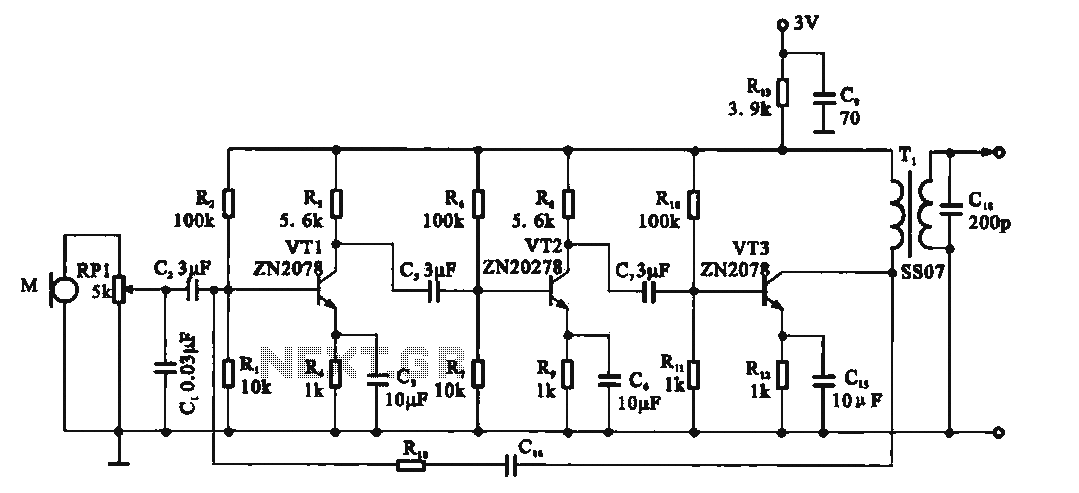
This circuit is a recording signal amplifying transistor circuit that illustrates the functioning of a microphone signal amplifier. After adjustment through potentiometer RP1, the signal is applied to the transistor VT1, which operates as a common emitter amplifier. The...