
Switched-mode-motor-speed-controller
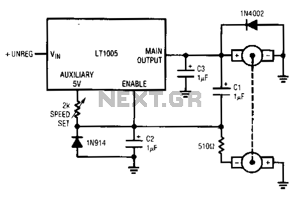
This circuit utilizes a tachometer to generate a feedback signal that is compared to a reference provided by the auxiliary output. Upon power application, the tachometer output is initially zero, allowing the regulator output to activate and supply current to the motor. As the motor begins to rotate and its speed increases, the negative output from the tachometer pulls the enable pin toward ground. Once the threshold voltage of the enable pin is reached, the regulator output diminishes, causing the motor to decelerate. Additionally, Cl provides positive feedback to ensure clean transitions. Consequently, the motor's speed is servo-controlled based on the setting of a 2-KΩ potentiometer. The regulator operates at the necessary frequency and duty cycle to keep the enable pin at its threshold. The loop's bandwidth and stability are determined by capacitors C2 and C3. A 1N914 diode is employed to prevent the negative tachometer output from lowering the enable pin below ground, while a 1N4002 diode is used to manage the motor's negative flyback pulse.
This circuit operates effectively by leveraging a feedback mechanism that integrates a tachometer and a regulator to control motor speed. The tachometer serves as a critical component by providing real-time speed feedback, which is essential for maintaining the desired operational parameters of the motor. The auxiliary output reference is crucial for establishing a baseline against which the tachometer's feedback can be measured.
The initial condition of the circuit, where the tachometer output is zero, indicates that the motor is not yet in motion. The regulator's activation at this point is vital as it initiates current flow to the motor, allowing it to start rotating. As the motor accelerates, the tachometer generates a negative voltage proportional to its speed, which is fed back into the control loop. This feedback mechanism is critical for achieving stability in motor speed control.
The enable pin acts as a threshold control point, and its behavior is influenced by the negative feedback from the tachometer. When the tachometer output reaches a level that pulls the enable pin low enough to cross its threshold voltage, the regulator automatically reduces its output. This dynamic adjustment is what allows the circuit to maintain a steady motor speed, effectively creating a closed-loop control system.
The use of the 2-KΩ potentiometer allows for user-defined speed settings, providing flexibility in motor operation. The positive feedback from capacitor Cl enhances the response time of the system, ensuring that transitions between different speed settings are smooth and without oscillations.
Capacitors C2 and C3 play a critical role in defining the loop's bandwidth and stability. Proper selection of these components is essential to ensure that the system responds adequately to changes in motor speed without introducing instability or excessive overshoot.
The inclusion of diodes, specifically the 1N914 and 1N4002, adds protection and enhances the reliability of the circuit. The 1N914 diode prevents the enable pin from being driven below ground, which could lead to erratic behavior or damage. Meanwhile, the 1N4002 diode serves to safeguard the circuit against voltage spikes generated by the motor's inductive load during operation, particularly during the switching off phase when negative flyback pulses can occur.
Overall, this circuit exemplifies a robust design for motor speed control, effectively combining feedback mechanisms, user control, and protective elements to achieve reliable performance in various applications.This circuit uses a tachometer to generate a feedback signal which is compared to a reference supplied by the auxiliary output. When power is applied, the tachometer output is zero and the regulator output comes on, forcing current into the motor.
As motor rotation increases, the negative tachometer output pulls the enable pin toward ground. When the enaole pin"s threshold voltage is reached, the regulator output decreases and the motor slows. Cl provides positive feedback, ensuring clean transitions. In this fashion, the motor"s speed is servo-controlled at a point determined by the 2-KO potentiometer setting. The regulator free-runs at whatever frequency and duty cycle are required to maintain the enable pin at its threshold.
The loop bandwidth and stability are set by C2 and C3. The 1N914 diode prevents the negative output tachometer from pulling the enable pin below ground, and the 1N4002 commutates the motor"s negative flyback pulse. 🔗 External reference