
Symmetrical power supply circuit electronic project
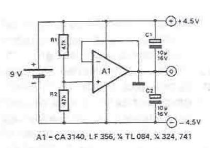
The circuit for a symmetrical power supply typically consists of an operational amplifier configured in a non-inverting mode, with resistors R1 and R2 forming a voltage divider network. The primary function of the operational amplifier in this configuration is to maintain a stable reference voltage at its non-inverting input, which is derived from the voltage divider formed by R1 and R2.
In this setup, R1 is connected from the positive supply voltage to the inverting input of the operational amplifier, while R2 is connected from the inverting input to ground. The output of the operational amplifier is fed back to the inverting input, creating a closed-loop feedback system. This feedback mechanism is essential for ensuring that the voltage at the inverting input matches the voltage at the non-inverting input, thus stabilizing the output voltage.
The output voltages of the symmetrical power supply are determined by the values of R1 and R2. When R1 and R2 are equal, the output voltages will be equal in magnitude but opposite in polarity, achieving a symmetrical output. This symmetry is critical for applications requiring balanced power supply rails, such as in audio amplifiers, operational amplifier circuits, and analog signal processing.
To further enhance the performance of the symmetrical power supply, it may be beneficial to add bypass capacitors at the power supply pins of the operational amplifier. This addition helps to filter out high-frequency noise and provides a more stable voltage reference. Additionally, incorporating a precision voltage reference can improve the accuracy of the output voltages.
Overall, this symmetrical power supply circuit is a fundamental design that leverages the properties of operational amplifiers and resistive voltage dividers to achieve balanced output voltages suitable for various electronic applications.A symmetrical power supply, can be designed using this circuit diagram. This symmetrical power supply is designed using a simple operational amplifier and some classic electronic components Resistances R1 and R2 form a high impedance voltage divider. Operational amplifier makes sure that artificial potential mass is the same as the voltage at the common point between R1 and R2. The ratio of R1 and R2 determine the relationship between the two output voltages, if R1 and R2 are identical, the two output voltages are symmetrical. 🔗 External reference
Related Circuits
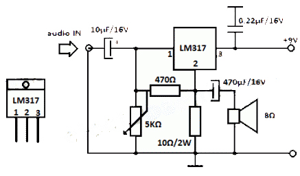
The LM317 integrated circuit (IC) is commonly recognized as a voltage regulator; however, it can also function as an audio amplifier. This low-power amplifier circuit designed with the LM317 provides a maximum output of approximately 1 watt. The LM317...
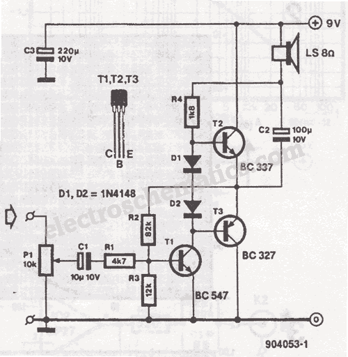
This miniature audio amplifier provides an output of up to 250mW and can function as a final stage audio amplifier for radio sets. The schematic is straightforward, featuring one BC transistor. The described miniature audio amplifier is designed for efficient...
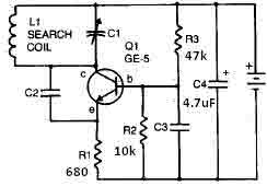
This metal detector circuit needs to be powered using a 9 volts power supply (DC) or a 9 volts battery. The C1 capacitor is a variable capacitor with a value of 365 pF, C2 is a 100 pF silver...
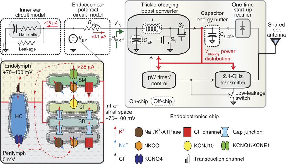
To generate and maintain the endocochlear potential (EP), perilymphatic potassium ions (K+) enter fibrocytes (F) through the Na+/K+-ATPase and Na-K-Cl cotransporter. Gap junction networks connect fibrocytes to strial basal (SB) and intermediate (SI) cells, allowing ions to enter the...
This is a simple mains power failure alarm circuit that activates an alarm when the mains supply is lost. Unlike many similar circuits, this design does not require a backup power source, such as a battery, to operate the...
This is a circuit of a step-down charge pump regulator for USB-powered devices. The critical design parameter of this circuit is the circuit area. The step-down charge pump regulator is designed to efficiently convert a higher input voltage from...
Warning: include(partials/cookie-banner.php): Failed to open stream: Permission denied in /var/www/html/nextgr/view-circuit.php on line 713
Warning: include(): Failed opening 'partials/cookie-banner.php' for inclusion (include_path='.:/usr/share/php') in /var/www/html/nextgr/view-circuit.php on line 713