
synchronizing fireflies ng
The circuit design is based on a microcontroller that facilitates the autonomous operation of each firefly unit, allowing for real-time interaction and adjustment based on local stimuli. The microcontroller is programmed to handle the threshold logic for flash power accumulation and reset, as well as the detection of other flashes via the light sensor. The light sensor, whether a photoresistor or phototransistor, plays a crucial role in determining the ambient light conditions and the timing of the flashes.
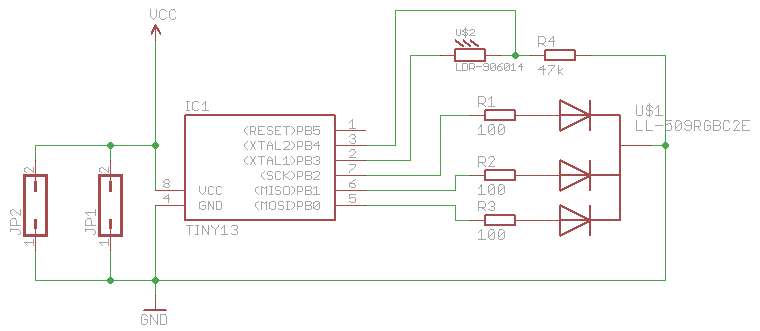
The voltage divider formed by the light sensor and resistor R4 is essential for scaling the sensor's output to a level suitable for the microcontroller's ADC input. The choice of R4 is critical; it must be selected to provide an appropriate voltage range while limiting current through the sensor to prevent damage. The use of a phototransistor, specifically the SFH 3310, enhances the circuit's responsiveness and accuracy in detecting light changes, which is vital for maintaining synchronization among the fireflies.
The RGB LED serves as the visual output, changing colors based on the synchronization status of the fireflies. The design encourages the use of clear LEDs with a roughened surface to maximize light dispersion, enhancing the visual effect of the flashing. The entire system operates on a 5V power supply, which simplifies the design but requires careful management of power consumption and component ratings.
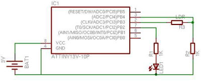
Overall, this circuit not only simulates the fascinating phenomenon of firefly synchronization but also provides a platform for exploring concepts of emergent behavior, self-organization, and interactive electronic design. The project exemplifies the intersection of art and technology, resulting in a captivating display that evolves with each interaction.This is a remake of the fireflies which I did a year ago. I was always fascinated by the emergence of patterns. One I like most is the synchronization of hundreds or thousands of fireflies. First they flash randomly but after some time and influencing each other, they flash in sync. This circuit simulates fireflies with small microcontrollers. Not e that every firefly acts completely autonomously, it is not a preprogrammed pattern. It is a self organizing system. Each firefly has a value that stands for the power to flash. This value rises over time. If the power reaches a certain limit, the firefly flashes and the power is reset to zero. If the firefly detects another flash nearby, it increases the power by a small boost value. That way it will flash slightly earlier than last time. Doing so over and over again may lead to all fireflies flashing in sync. The RGB-firefly uses color to express its mood. If all is in sync, it will flash in relaxed and cool blue. If it detects flashes that are not in sync, it will get a bit uncomfortable and the color will slightly change to green, yellow and red. The circuit is rather simple. Main parts are the microcontroller, the light sensor and the RGB-LED. The sensor and R4 are forming a voltage divider. An ADC (Analog Digital Conversion) channel at pin 3 is used to read the values of the sensor. The circuit is designed for 5V power supply. It has no integrated power regulator. Various types of photoresistors exist. I tried two different versions and both work well. Only resistor R4 has to be adjusted, as R4 and the photoresistor are building a voltage divider. Choose R4 in a way, that gives you a good range of voltage and still limits the current through the photoresistor.
My latest experiments showed that a phototransistor seems even better suited. Compared to the LDR, it does not have a memory effect and reacts faster (~5ms compared to ~50ms). I chose the SFH 3310 and 100k for R4. One thing to remember while choosing a light sensor, is that the spectral sensitivity of the sensor has to match the humans eye sensitivity (~400 nm ~700 nm). Next insert the LDR. For the LDR the orientation does not matter. For the phototransistor it does! The phototransistor has a long (emitter) and a short leg (collector). Insert it with the long leg at the bottom. And solder it. Now prepare the LED. Mine are clear and have a lens on top. Use sandpaper to roughen the surface. That way the light of the LED will be emitted in all directions. Playing with these fireflies is really mesmerizing. It`s not like most computer controlled things because it is non deterministic. Every time you start it, it will produce new patterns and behave differently. I am quite happy how well the PCB worked out. It was my second design that I have had produced. Now I am feeling confident enough to go for a bigger batch of PCBs. 🔗 External reference
Related Circuits
This application note provides insight into how to synchronize multiple high-speed DACs in transmitter applications. This document outlines the techniques and methodologies for synchronizing multiple high-speed Digital-to-Analog Converters (DACs) in various transmitter applications. Synchronization is crucial in systems where multiple...
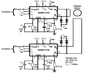
The schematic below represents a typical stepper motor driver application utilizing the NJM3770A. As illustrated in the diagram, the single-channel stepper motor drivers NJM3717 and NJM3770A operate independently and are not synchronized. The circuit design features the NJM3770A, a dedicated...

When first discovering this article, it was noted that it is a great project utilizing only a few components. Microcontroller projects based on LEDs are of particular interest. This project is very simple and worth trying. It is inspired...
When first encountering this article, it is apparent that it presents an excellent project utilizing only a few components. Microcontroller projects based on LEDs are particularly appealing. This project involves the design and implementation of a microcontroller-based LED circuit, which...