
Tape recorder interface
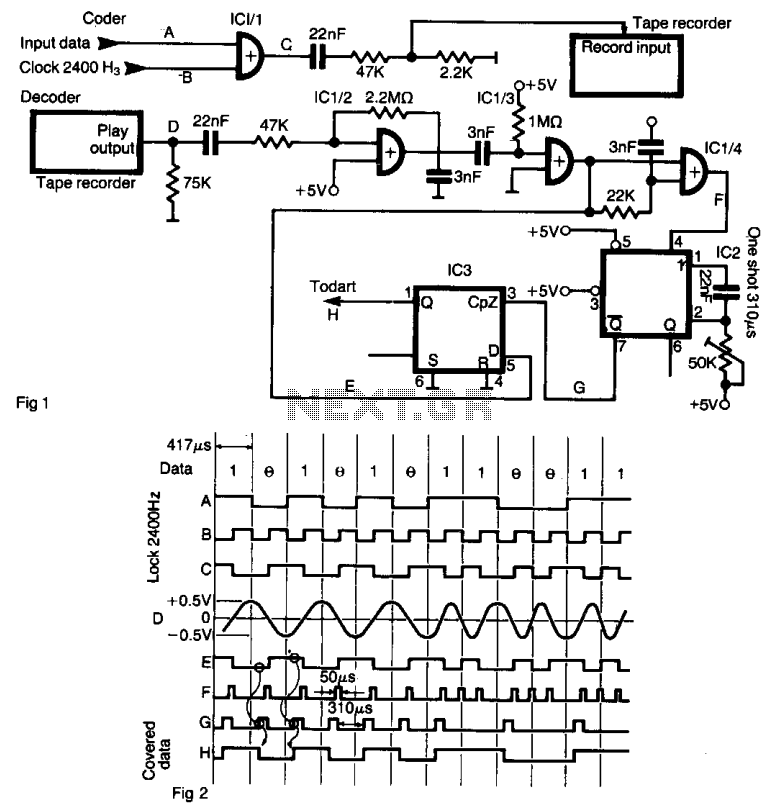
The described circuit utilizes a series of integrated circuits (ICs) to facilitate the encoding and decoding of data for storage on magnetic tape. The XOR gate (IC 1/1) is essential for modulating the data stream with the clock signal, ensuring that the recorded signals maintain synchronization with the timing reference. The amplitude adjustment before sending the signal to the tape recorder is crucial, as it prevents distortion and ensures reliable playback.
During playback, the CMOS gate (IC 1/2) amplifies the incoming pulses to a level suitable for further processing. The linear amplifier configuration allows for a faithful reproduction of the recorded data, ensuring that the TTL signal levels are achieved for subsequent digital processing.
The use of IC 1/4 to create short pulses upon detecting transitions in the signal is an effective method for capturing the rapid changes in the data stream. This functionality is critical for accurately representing the original data, especially in sequences of identical bits, where the one-shot timer (IC 2) must be retriggered to avoid missing transitions.
The D-type flip-flop (IC 3) serves as a memory element, capturing the state of the data stream at precise moments dictated by the pulse widths generated by IC 2. This allows for the reconstruction of the original data sequence at the output, which can then be processed by the Z80 DUART. The configuration of the DUART to operate at 38.4 kHz, which is 16 times the data rate, ensures that the data can be reliably received and processed without errors, facilitating efficient communication in digital systems. Overall, this circuit design showcases a practical approach to data storage and retrieval using analog media, leveraging digital logic components to achieve reliable performance.The interface allows data to be saved on an ordinary tape recorder at a speed of 2400 bit/s. The serial stream of data Fig. 1 (A) is coded with a clock of 2400 Hz (B), by means of XOR gate IC 1/1. Logical "high" and "low" appear as shown in Fig. 2 (C). These impulses are lowered in amplitude and feed into the record input of a low cost tape recorder. During the playback, pulses (D) are amplified with CMOS gate IC 1/2 connected as a linear amplifier, and providing a TTL level signal shown in (E). On both positive and negative transitions IC 1/4 forms short pulses as shown in (F) (approx. 50 *ts) that triggers one shot IC2. A monostable one shot pulse width is adjusted to be 3A of bit length (310 µß). A change from "high" to "low" in a coded stream generates a "low" pulse width of one bit cell. The same is for change from ' low'' to ' 'high'' that generates a "high" pulse of the same width. During this pulse one shot latches the state of line in D type flip-flop IC3 (G). When a stream consists of multiple "ones" or "zeros," the one shot is retriggered before it comes to the end of the quasistable state and the state of the flip-flop remains unchanged. The original data stream is available at the output of the flip-flop (). Z80 the DUART that receives these pulses is programmed so that the receiver clock is 16 times the data rate (38.4 kHz).
🔗 External reference
Related Circuits
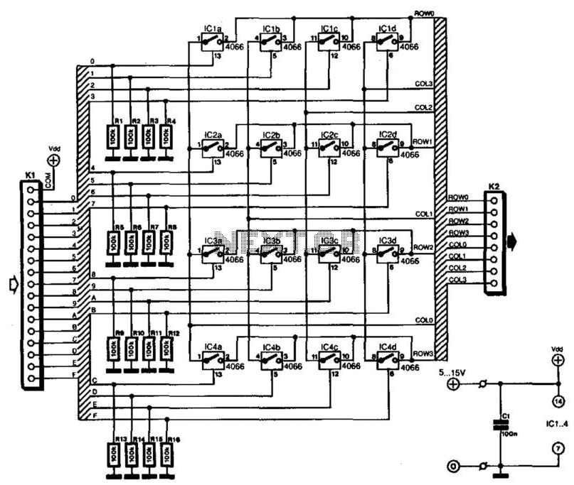
Keyboards can be classified into two categories based on the connection method of the switches: those with a common connection and those arranged in a matrix. The matrix type offers the significant advantage of minimizing the number of connections,...
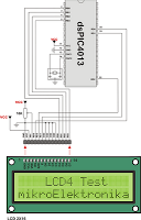
The 2x16 Parallel LCD is an 8-bit or 4-bit parallel interfaced LCD. This unit allows the user to display text, numerical data, and custom-created characters. The LCD utilizes the HD44780 series LCD driver from Hitachi or an equivalent controller....
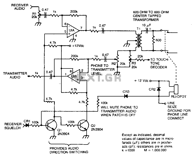
This circuit facilitates the communication link between the receiver and the phone line, as well as the phone line and the transmitter, utilizing an operational amplifier (op-amp) for signal amplification. The described circuit connects a receiver to a phone line...
Watching the time on a mobile phone in the dark can cause discomfort due to the strong contrast between bright and dark backlighting. To address this issue, the "ICON" model is utilized, which operates in standby mode with a...
The circuit connects a commercial DCF77 receiver, which is available for approximately $15, to a PC via the RS232 serial port. By modifying the program or the circuit, it is also possible to utilize different systems or I/O ports....
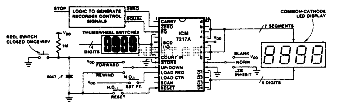
This circuit illustrates various applications of up/down counting for monitoring dimensional position. In the tape recorder application, the LOAD REGISTER, EQUAL, and ZERO outputs are utilized to control the recorder. To ensure the recorder stops at a specific point...
Warning: include(partials/cookie-banner.php): Failed to open stream: Permission denied in /var/www/html/nextgr/view-circuit.php on line 713
Warning: include(): Failed opening 'partials/cookie-banner.php' for inclusion (include_path='.:/usr/share/php') in /var/www/html/nextgr/view-circuit.php on line 713