
TDA2030 200 watt amp low cost audio power amplifier
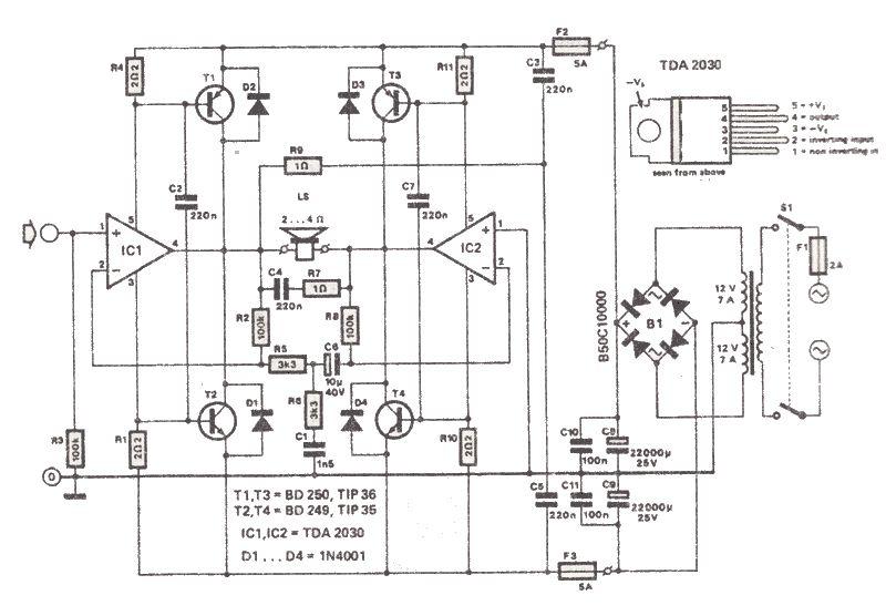
The TDA2030 audio amplifier IC is widely used in various audio amplification applications due to its efficiency and performance. In bridge mode configuration, the amplifier utilizes two TDA2030 ICs, where one operates as a positive output and the other as a negative output. This arrangement effectively doubles the output voltage, thereby increasing the power delivered to the load.
The circuit typically includes a power supply capable of delivering sufficient current to support the high output demands. A dual power supply with positive and negative voltage rails is often used to provide the necessary voltage levels for the TDA2030 in bridge mode. Capacitors are included at the power supply input to filter out noise and stabilize the voltage.
In addition to the TDA2030 ICs, the circuit design incorporates several discrete components, including power transistors that handle the higher output power. These transistors are selected based on their voltage and current ratings to ensure they can handle the demands of the amplifier without failure. Proper biasing of these transistors is crucial for optimal performance and linearity.
Heatsinks are critical in this design to dissipate heat generated by the ICs and transistors during operation. The thermal management strategy must account for the maximum power output and the ambient conditions in which the amplifier will operate. Adequate airflow around the heatsinks is necessary to maintain safe operating temperatures.
Resistors used in the circuit, particularly those with low resistance values (such as 1 ohm and 2.2 ohms), should be rated for higher wattage (2 to 5 watts) to handle the power dissipation without overheating. Proper resistor selection is vital for maintaining circuit stability and performance.
Overall, this TDA2030-based amplifier circuit offers a cost-effective solution for achieving high audio power output, making it suitable for various audio applications where budget constraints are a consideration. The design emphasizes the importance of thermal management and component selection to ensure reliable and efficient operation.This TDA2030 200 watt amp low cost audio power amplifier can deliver high output audio power up to 200 watts on a 2 4 ohms load impedance. This 200 watt amp high power audio amplifier is build around the TDA2030 audio amplifier IC which normally can deliver up to 14 watts on a 4 ohm load, but if is used in bridge mode an if we use some cheap
power transistors can be created a 200 watts high power audio amplifier. All transistors and the ICs must be mounted on a heatsink to prevent over temperature damage. For small value resistors ( 1 ohm, 2. 2 ohms ) use 2 -5 watts resistors. 🔗 External reference
Related Circuits
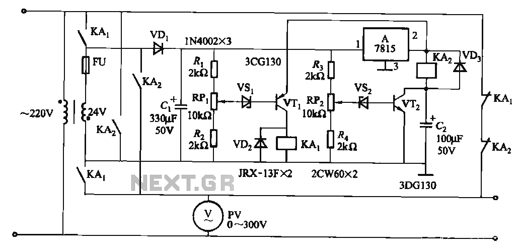
When the input voltage is in the range of 170-260V AC, the output AC voltage falls between 187-231V. The transformer ratio is k = 24/220 = 0.11. If the input voltage drops below 170V, relay KAi activates (adjusted by...
That circuit protects the overdriven signals going into an amplifier. Instead of a zener diode, we use a transistor. That way we ensure that the above the ordinary input voltages (1 volt r.m.s.) can be achieved without distortion. Also,...
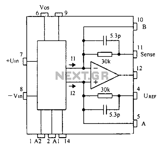
Based on the CNC programming, a gain instrumentation amplifier circuit diagram utilizing the PGA202/203 is presented. The PGA202/203 series of programmable gain amplifiers are designed for high-performance applications requiring precise signal amplification. These integrated circuits offer a wide range of...
This UHF antenna amplifier circuit, also referred to as a UHF antenna booster circuit, is designed to amplify signals within the UHF band, specifically from 400 MHz to 850 MHz. The circuit employs a single transistor and provides an...
You need a power supply for a project, but only have a DC adapter available, so you can't use my AC power adapter trick (Project 05). This little project came about because a reader had just this problem, and...
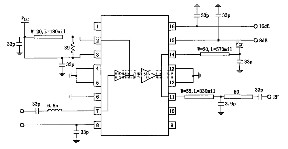
The circuit diagram illustrates the application of a 915MHz RF2155 power amplifier. The radio frequency (RF) signal enters through pin 7, where it is processed by a preamplifier. The output from the preamplifier is further amplified by the power...