
TDA7000 FM Radio IC Test Circuit and Datasheet
The TDA7000 integrated circuit is engineered for use in FM radio applications, providing a compact solution that integrates multiple essential functions into a single chip. The Frequency-Locked Loop (FLL) system allows for stable frequency tuning, which is crucial for maintaining clear audio reception. The RF input stage amplifies incoming radio signals, ensuring that weak signals can be adequately processed.
The mixer component within the TDA7000 combines the RF signal with a local oscillator signal to produce an intermediate frequency (IF) of 70 kHz. This IF signal is then demodulated by the IF demodulator to extract the audio information, which can subsequently be amplified for output. The mute detector and mute switch functionalities enable the radio to automatically mute the audio output during periods of weak signal reception or silence, enhancing the user experience by reducing unwanted noise.
In terms of physical design, the TDA7000 is typically implemented on a printed circuit board (PCB), where careful attention must be paid to the component layout to minimize interference and optimize performance. The datasheet provides comprehensive details on the recommended PCB layout, including the placement of components to ensure signal integrity and reduce parasitic effects.
Additionally, the package outline information is crucial for ensuring compatibility with existing designs and for proper thermal management. The maximum permissible temperature for soldering is specified to prevent damage to the IC during assembly. Repairing soldered joints is also addressed in the datasheet, providing guidance on best practices to ensure reliable connections and maintain performance over the lifespan of the device.
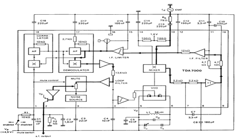
Overall, the TDA7000 serves as a versatile and efficient solution for FM radio applications, with its integrated design simplifying the development process for engineers and hobbyists alike.TDA7000 is an IC for FM portable radios which has a Frequency-Locked-Loop system with an intermediate frequency of 70kHz. The TDA7000 has the following functions: RF input stage, mixer, local oscilator, IF demodulator, mute detector and mute switch.
The diagram below shows you with the block diagram of this FM radio monolithic IC. For printed-circ uit boards, component layout used for the circuit, package outline, maximum permissible temperature of the solder, and repairing soldered joints can be seen in the TDA7000 datasheet (source: nxp. com) 🔗 External reference
Related Circuits
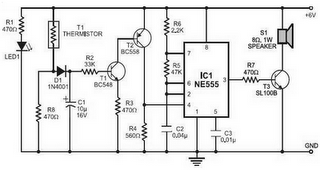
Fire alarm circuit using an LDR (Light Dependent Resistor) as a flame sensor. It warns the user about fire accidents by detecting smoke produced during a fire. As smoke passes between an LED and an LDR, the amount of...
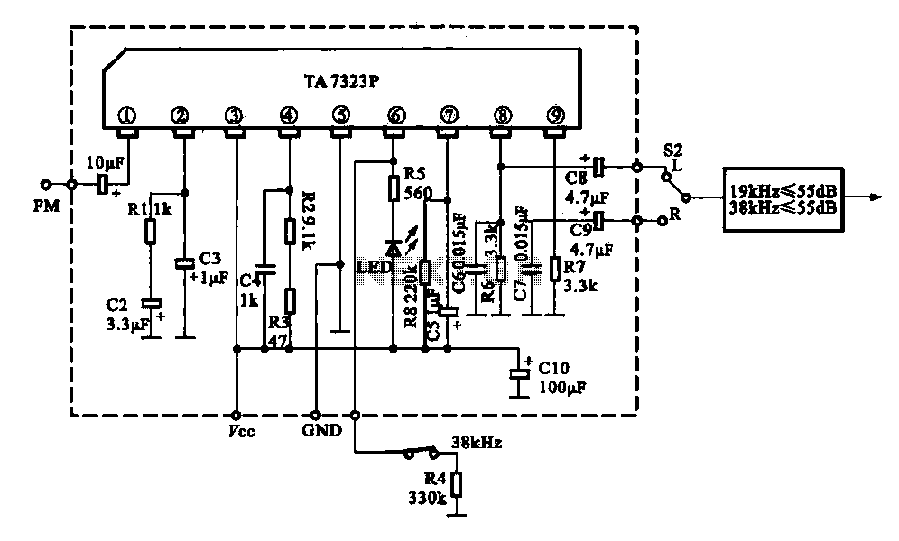
The current design utilizes a stereo decoder integrated circuit (IC) that guarantees a channel separation of 45 dB or more due to its manufacturing process. The intermediate frequency amplifier gain is sufficiently high to achieve a channel separation greater...
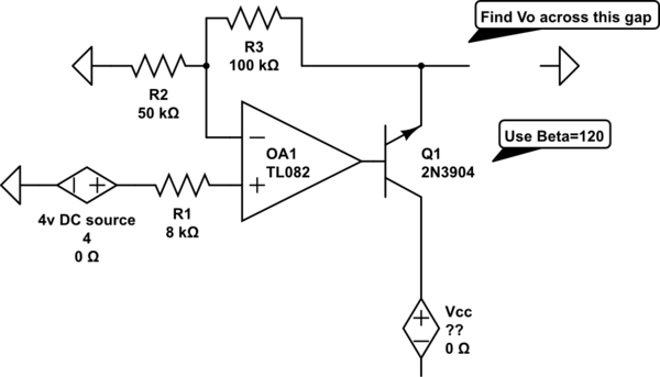
The voltage measured at 12V after the emitter is perplexing, especially when the output from the op-amp is +15V, suggesting a 3V drop across the transistor. This raises questions about the expected gain of 2, which would imply an...
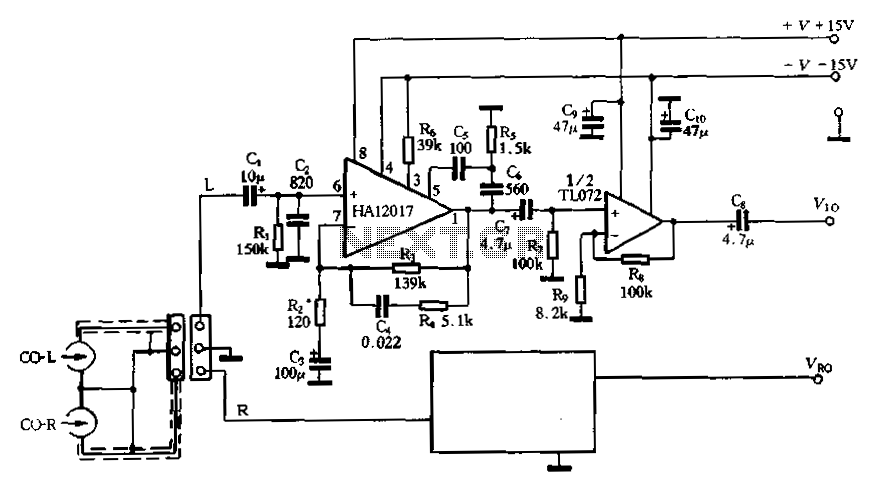
Figure 3-16 illustrates a low-noise preamplifier equalizing circuit using the HA12017. This circuit includes playback components R3, R4, and C4, which conform to a standard balanced network. The gain of the circuit is -7dB at 1kHz, while the output...
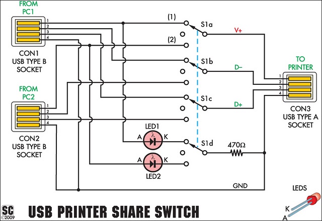
This device enables two computers to share a single USB printer or other USB devices such as an external flash drive, memory card reader, or scanner. A rotary switch is used to select the PC that will connect to...
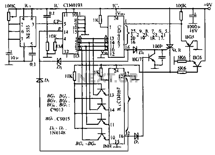
The circuit consists of an oscillator, a counter, and an Iseki circuit divided into three parts. The oscillator is based on the NE555 timer and several external RC components, generating a pulse signal for the counter. The instantaneous power...