
TDA7056 audio amplifier circuit diagram electronic project
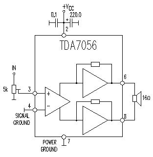
The TDA7056 is a low-voltage audio amplifier IC that is commonly used in portable audio applications due to its compact size and efficiency. The circuit typically includes the TDA7056 IC, which is the core component responsible for amplification. The input signal is fed into the IC, and the output is taken across the load, which can be a speaker or similar audio device.
To construct this audio amplifier, two capacitors are used for coupling and decoupling purposes. The first capacitor is typically placed at the input to block any DC offset from the audio source, ensuring that only the AC audio signal is amplified. The second capacitor is used at the output to filter out any unwanted high-frequency noise, providing a cleaner audio signal to the speaker.
The resistor in the circuit is usually employed to set the gain of the amplifier, allowing for adjustment of the output volume. The choice of resistor value will affect the overall performance of the amplifier, including its gain and distortion characteristics.
The TDA7056 is designed to operate efficiently without the need for a heatsink, making it suitable for battery-powered devices where space and weight are critical considerations. This feature simplifies the design and assembly process, allowing for a more compact and lightweight audio amplifier solution.
Overall, this circuit is ideal for hobbyists and engineers looking to create a simple yet effective audio amplification solution for various applications, such as portable speakers, radios, and other audio devices.This TDA7056 power audio amplifier electronic circuit diagram project will provide a maximum output power of 1 watt into a 8 ohms load using a 6 volts power supply, or a maximum output power of 3 watts into a 16 ohms load using a 11 volts power supply. As you can see in the circuit diagram you will need just two capacitors and one resistor to co nstruct this audio amplifier. The TDA IC don`t need to be mounted on a heatsink. 🔗 External reference
Related Circuits
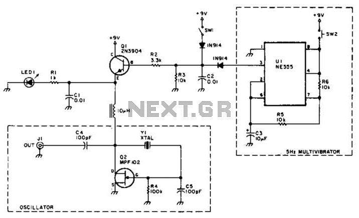
A useful marker oscillator can be constructed using an NE555 timer to generate pulses at an audio frequency. This design facilitates the detection of the signal even amidst interference. The crystal frequency can range from 1 to 30 MHz. The...
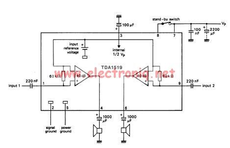
The TDA1519 circuit can deliver 2x6 watts output power. TDA1519 is an integrated class-B dual output amplifier in a 9-lead single in-line (SIL) plastic medium power package primarily developed for car radio applications. The TDA1519 is a robust integrated circuit...
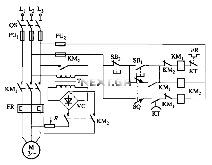
The circuit illustrated in Figure 3-136 incorporates a limit switch (SQ) that, when the motor operates a mechanical device to reach a predetermined position, cuts off the power and initiates dynamic braking for fast and accurate positioning. This configuration...
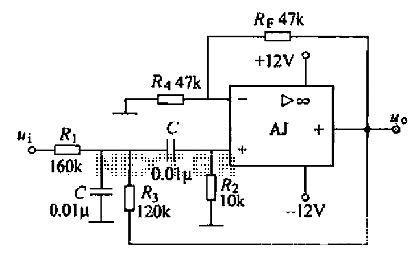
A band-pass filter permits only signals within a specified frequency range to pass through, while attenuating or suppressing those outside this range. This is characterized by a lower frequency limit and an upper frequency limit. A typical implementation is...
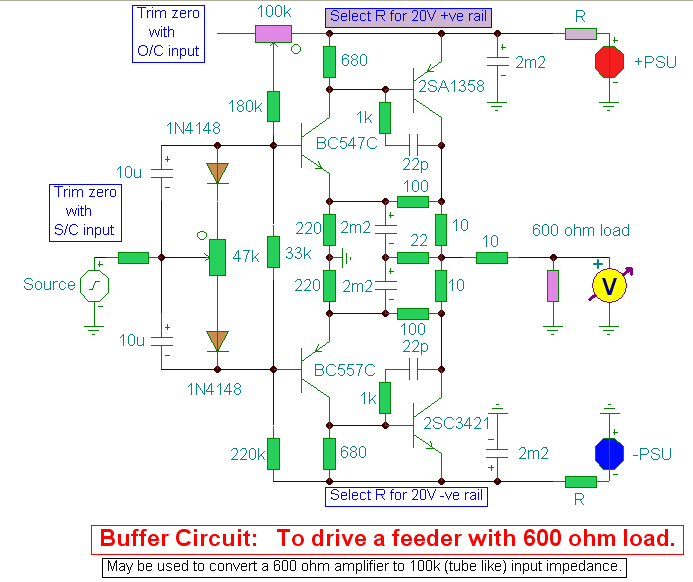
A hi-fi preamplifier designed to convert high output impedance amplifiers to 600-ohm outputs. The described hi-fi preamplifier is engineered to facilitate the interfacing of high output impedance audio sources with low impedance loads, specifically targeting a standard output impedance of...
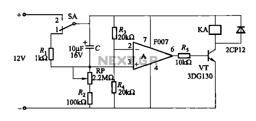
A delay circuit utilizing an operational amplifier functions as a comparator, providing high timing accuracy. The timer's delay range is from 1 to 30 seconds. The delay time is determined by resistors Ri, RP, and capacitor C. By adjusting...