
tda7338 fm stereo decoder circuit

The open collector output configuration allows for multiple devices to connect to a single line without interfering with each other, making it suitable for various applications, including signal detection and logic level interfacing. An external pull-up resistor is necessary to pull the output high when the transistor is not conducting. The value of this resistor should be chosen based on the desired pull-up speed and the load connected to the output.
In the case of the pilot detector, when the output is inactive (the transistor is off), the pull-up resistor will pull the voltage to the supply level, typically Vcc. When the output is active (the transistor is on), it will connect the output to ground, allowing the voltage to drop to a low state.
To force the decoder into "MONO" mode, it is crucial to clamp Pin 19 to a voltage below 0.8V. This can be achieved using a diode or a resistor divider that ensures the voltage at Pin 19 does not exceed this threshold. Clamping prevents potential damage to the decoder and ensures proper operation by keeping the input within specified voltage levels.
In summary, the pilot detector's open collector output and the requirement for clamping Pin 19 are critical for ensuring reliable operation of the decoder in mono mode. Proper selection of the pull-up resistor and clamping method is essential for achieving desired performance and protecting the circuit components.The pilot detector output is designed as an open collector output, therefore an external pull up resistor is needed. To force the decoder to "MONO" Pin 19 has to be clamped to a voltage below 0. 8V. 🔗 External reference
Related Circuits

The transmitter is constructed on a Printed Circuit Board (PCB). This board incorporates track inductors for L1, L2, and part of L3. The section surrounding Q1 functions as the oscillator section, with the oscillation frequency determined by L1, C4,...
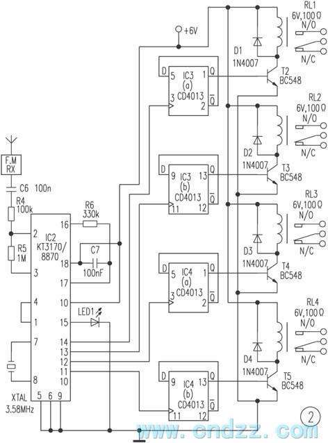
The remote control transmitter consists of a DTMF generator and an FM transmitter circuit. A UM91214B phone-specific integrated circuit (IC) is utilized to generate the DTMF signal, with a 3V power supply provided by a 3V zener diode (D1)....
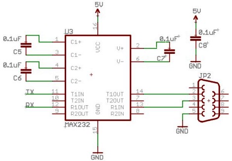
Select a free schematic drawing software that resembles the two mentioned. There have been discussions regarding circuit drawing software. Fritzing is favored, although it lacks certain components, such as the RS232 component. There is a request for feedback on...

This scan is from an old ETI Circuits #2 publication from the 1970s. It contains valuable operational amplifier information that is highly useful. With some knowledge, the six circuits presented serve as an instant reference, enabling various applications. These...

An automatic light control circuit is designed to illuminate a lamp when it is dark and to turn off the light at daybreak. The circuit, as shown in Figure 2-86, employs bidirectional thyristor tubes and features a straightforward design....
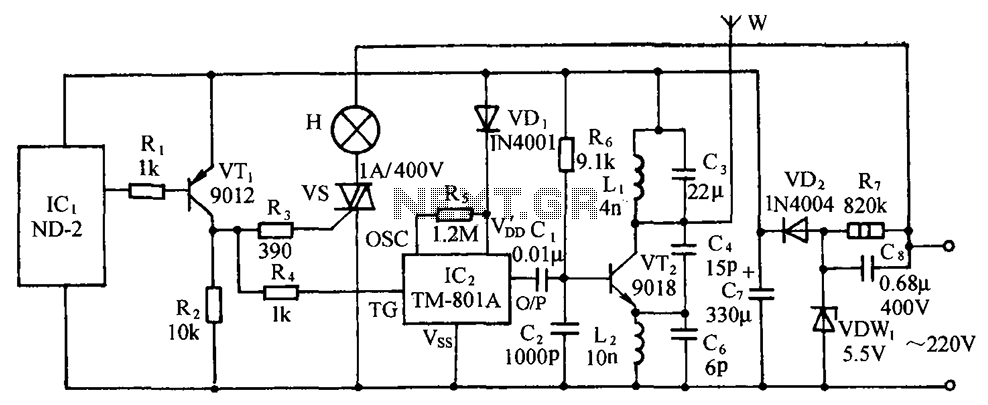
The circuit includes a comprehensive array of components such as vibration sensors, a follower, a lamp relay control circuit, a voice sounding circuit, a high-frequency oscillation circuit, and an AC rectifier buck power supply circuit. The vibration sensor is...
Warning: include(partials/cookie-banner.php): Failed to open stream: Permission denied in /var/www/html/nextgr/view-circuit.php on line 713
Warning: include(): Failed opening 'partials/cookie-banner.php' for inclusion (include_path='.:/usr/share/php') in /var/www/html/nextgr/view-circuit.php on line 713