
Telephone-amplifier
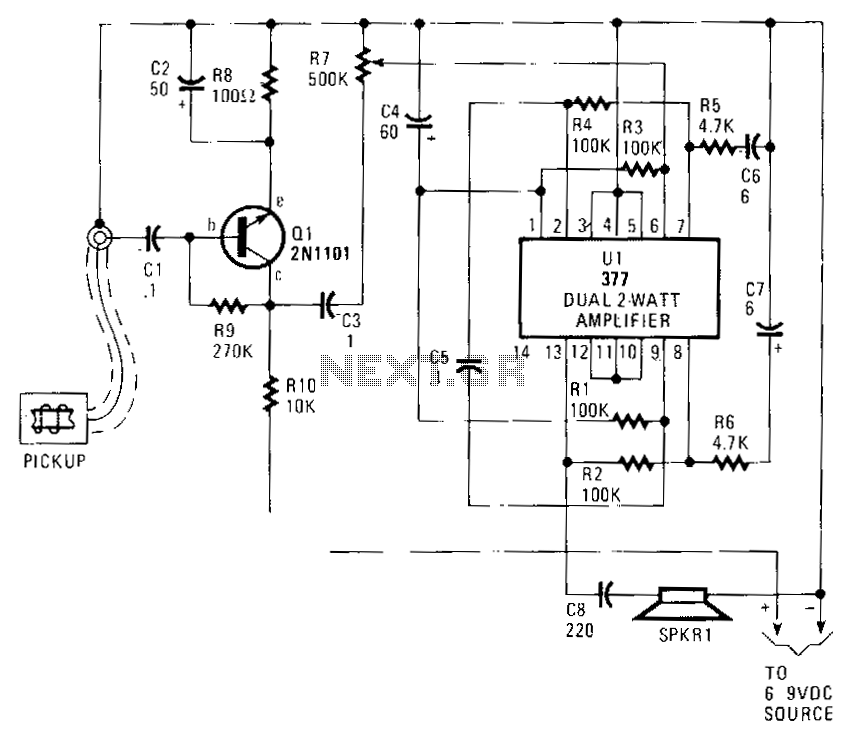
Audio from the telephone is inductively coupled to the base of Q1, which functions as a preamplifier. This preamplifier provides a gain of approximately 75 dB, boosting the input signal from around 4 mV to about 300 mV peak-to-peak. If a higher gain transistor is utilized, the value of R9 should be increased to establish a Q point, measured from the negative supply to the collector of Q1, at half the supply voltage. The output signal from Q1 is coupled through C3 to R7, which acts as a volume or drive-level control, leading to U1, a dual 2 W amplifier configured in cascade. Pins 1 through 7 act as a driver for the final amplifier, while pins 8 through 13 are designated for the final amplification stage. Compensation and balance are achieved using components R1 through R6 and C4, C6, and C7. Pins 3 through 5 and 10 through 12 should be connected to the negative supply rail.
The described circuit operates as an audio amplification system designed to enhance telephone audio signals. The inductive coupling from the telephone to the base of transistor Q1 allows for efficient signal transfer without the need for direct electrical connections. The preamplifier stage, utilizing Q1, is crucial for elevating the weak audio signal, which typically measures around 4 mV, to a more usable level of approximately 300 mV peak-to-peak. This significant gain of 75 dB is achieved through careful selection of the transistor and biasing components.
In cases where a higher gain is desired, adjustments to the resistor R9 are necessary. This resistor plays a vital role in setting the operating point (Q point) of the transistor, ensuring that it operates within its optimal range. The Q point is defined as being half of the supply voltage, which is important for maximizing the linearity and efficiency of the amplification process.
The output from the preamplifier is then coupled to R7 through capacitor C3. The resistor R7 serves as a volume control, allowing for modulation of the output signal level before it is sent to the power amplifier stage. U1, the dual 2 W amplifier, is configured to amplify the signal further. The first seven pins of U1 are designated for the driver stage, which prepares the signal for the final amplification stage, utilizing pins 8 through 13.
To ensure that the amplifier operates correctly and maintains audio fidelity, compensation and balance are addressed through the use of resistors R1 to R6 and capacitors C4, C6, and C7. These components work together to stabilize the amplifier's response and minimize distortion. Additionally, connecting pins 3 through 5 and 10 through 12 to the negative supply rail is crucial for proper operation, as it provides the necessary reference point for the amplifier's circuitry.
In summary, this audio amplification circuit effectively enhances telephone audio signals through a multi-stage amplification process, utilizing inductive coupling, precise biasing, and careful component selection to achieve high-quality audio output.Audio from the telephone is inductively coupled to the base of Ql. which is used as a preamp. The preamp provides a gain of about 75 dB, to boost the input signal from .about 4 mV to about 300 mV pk-pk. If you use a higher gain transistor, increase the value of R9 to produce a Q point, measured from minus to the collector of Ql, of one-half the supply voltage.
The Ql output signal is coupled through C3 to R7, which serves as a volume or drive-level control, to Ul, a dual, 2 w amplifier connected in cascade. Pins 1 through 7 serve as a driver for the final amplifier, pins 8 through 13. Compensation and balance is accomplished by components R1 through R6 and C4, C6, and C7. Pins 3 through 5, and 10 through 12 should be tied to the negative supply rail. 🔗 External reference