
Telephone call meter using calculator & COB

The circuit is simple and presents an elegant look, with feather-to uch operation. It consumes very low current and is fully battery operated. The batteries used last more than a year. Another advantage of using this circuit is that it is compatible with any type of pulse rate format, i. e. pulse rate in whole number, or whole number with decimal value. Recently, the telephone department announced changes in pulse rate format, which included pulse rate in whole number plus decimal value.
In such a case, this circuit proves very handy. To convert STD/ISD calls to local calls, this circuit needs accurate 1Hz clock pulses, generated by clock COB. This COB is found inside analogue quartz wall clocks or time-piece mechanisms. It consists of IC, chip capacitors, and crystal that one can retrieve from scrap quartz clock mechanisms.
These can be purchased from watch-repairing shops for less than Rs 20. Normally, the COB inside clock mechanism will be in good condition. However, before using the COB, please check its serviceability by applying 1. 5V DC across terminals C and D, as shown in the figure. Then check DC voltage across terminals A and B; these terminals in a clock are connected to a coil. If the COB is in good condition, the multimeter needle would deflect forward and backward once every second. In fact, 0. 5Hz clock is available at terminals A and B, with a phase difference of 90o. The advantage of using this COB is that it works on a 1. 5V DC source. The clock pulses available from terminal A and B are combined using a bridge, comprising diodes D1 to D4, to obtain 1Hz clock pulses.
These clock pulses are applied to the base of transistor T1. The collector and emitter of transistor T1 are connected across calculator s = terminals. The number of pulses forming an equivalent call may be determined from the latest telephone directory. However, the pulse rate (PR) found in the directory cannot be used directly in this circuit. For compatibility with this circuit, the pulse rate applicable for a particular place/distance, based on time of the day/holidays, is converted to pulse rate equivalent (PRE) using the formula PRE = 1/PR.
You may prepare a look-up table for various pulse rates and their equivalents (see Table). Suppose you are going to make an STD call in pulse rate 4. Note down from the table the pulse rate equivalent for pulse rate 4, which is 0. 25. Please note that on maturity of a call in the telephone exchange, the exchange call meter immediately advances to one call and it will be further incremented according to pulse rate. So one call should always be included before counting the calls. For making call in pulse rate 4, slide switch S1 to off (pulse set position) and press calculator buttons in the following order: 1, +, 0.
25, =. Here, 1 is initial count, and 0. 25 is PRE. Now calculator displays 1. 025. This call meter is now ready to count. Now make the call, and as soon as the call matures, immediately slide switch S1 to on (start/standby position). The COB starts generating clock pulses of 1 Hz. Transistor T1 conducts once every second, and thus = button in calculator is activated electronically once every second.
The calculator display After finishing the call, immediately slide switch S1 to off position (pulse set position) and note down the local call meter reading from the calculator display. If decimal value is more than or equal to 0. 9, add another call to the whole number value. If decimal value is less than 0. 9, neglect decimal value and note down only whole numbers. To store this local call meter reading into calculator memory, press M+ button. Now local call meter reading is stored in memory and is added to the previous local call meter reading.
For continuous display of current local call meter reading, press MRC button and slide switch S1 to on (start/standby position). The current local call meter reading will blink once every second. In prototype circuit, the author used TAKSUN calculator that costs around Rs 80. The display height was 1 cm. In this calculator, he substituted the two button-type batteries with two externally connected 1. 5V R6 type batteries to run the calculator for more than an year. The power off button terminals were made dummy by affixing cellotape on contacts to avoid erasing of memory, should someone accidentally press the power off button.
This calculator has auto off facility. Therefore, some button needs to be pressed frequently to keep the calculator on. So, in the idle condition, the = button is activated electronically once every second by transistor T1, to keep the calculator continuously on. Useful hints. Solder the = button terminals by drilling small holes in its vicinity on PCB pattern using thin copper wire and solder it neatly, such that the = button could get activated electronically as well as manually.
Take the copper wire through a hole to the backside of the PCB, from where it is taken out of the calculator as terminals G and H. At calculator s battery terminals, solder two wires to + and terminals. These wires are also taken out from calculator as terminals E and F. Affix COB on a general-purpose PCB and solder the remaining components neatly. For giving the unit an elegant look, purchase a jewellery plastic box with flip-type cover (size 15cm x 15cm).
Now fix the board, calculator, and batteries, along with holder inside the jewellery box. Then mount the box on the wall and paste the look-up table inside the box cover in such a way that on opening the box, it is visible on left side of the box. 🔗 External reference
Related Circuits
A line follower robot, abbreviated as LFR, is an autonomous robot designed to optically follow a line drawn on the floor. This involves the robot moving along an arbitrary line using a component known as a line sensor. A...
%2BCircuit%2Bdiagram%2Busing%2BCD4047%2Band%2BIRFZ44%2Bpower%2BMOSFET.png)
This simple low-power DC to AC inverter circuit converts 12V DC to either 230V or 110V AC. By making simple modifications, it is also possible to convert 6V DC to 230V AC or 110V AC. This inverter can be...
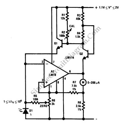
This is a portable light-level meter circuit with a five-decade dynamic range. It utilizes a single-cell battery as the power supply. To calibrate this circuit, The portable light-level meter circuit is designed to measure light intensity across a wide...
Cordless telephones are increasingly popular; however, they have a significant limitation: they cannot function during a power outage. To address this issue, a standard telephone is often connected in parallel to the cordless phone, which compromises privacy. A Uninterruptible...
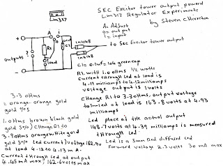
The following experiment demonstrates how Mr. Steven successfully extracted free energy from air using his home-built secondary exciter coil tower. He utilized this energy to power a small LM317 power supply unit. During the process, he hand-wound his coils...
This circuit is a simple buzzer circuit known as a novel buzzer. It utilizes a relay in series with a small audio transformer and a speaker. The relay will activate the circuit. The novel buzzer circuit operates by employing a...
Warning: include(partials/cookie-banner.php): Failed to open stream: Permission denied in /var/www/html/nextgr/view-circuit.php on line 713
Warning: include(): Failed opening 'partials/cookie-banner.php' for inclusion (include_path='.:/usr/share/php') in /var/www/html/nextgr/view-circuit.php on line 713