
Telephone-controlled-night-light
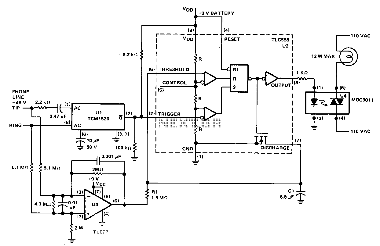
When the telephone rings or when the handset is lifted, the night light is activated and remains illuminated during the conversation. After the handset is replaced in the cradle, the light stays on for approximately 11 seconds. Under standby conditions, the -28 V DC bias on the phone line keeps the output of U3 in a high state. When the AC ringing signal is applied to the phone line, it is detected by ring detector U1, which generates a negative output pulse at pin 2 for each ring. These pulses trigger U2, resulting in its output becoming high and turning off the discharge transistor. The high output of U2 activates optoisolator U4, which powers the night light. Each ring retriggers the timer and discharges capacitor C1, preventing it from reaching the 2/3 V_nv threshold level. Consequently, the night light remains on while the phone is ringing and for about 11 seconds after the last ring. After this period, C1 charges to the U2 threshold level (2/3 V_nv), causing the output of U2 to return to a low state, which turns on its discharge output and discharges C1. The lamp will turn off if the phone is not answered. When the phone is answered, a 1 kΩ load is placed across the phone line, removing the differential input to operational amplifier U3, which causes its output to drop low, allowing capacitor C1 to discharge through resistor R1. As long as the voltage across C1 remains low, timer U2 cannot initiate its cycle, and the lamp will remain on. When the phone is hung up, the low impedance is removed from the phone line, leading to a differential voltage across the line that causes the output of U3 to become high. This allows C1 to start charging, initiating the timing sequence that will eventually turn off the night light.
The circuit operates by utilizing a combination of components to manage the illumination of a night light in response to telephone activity. The primary components include operational amplifiers, a timer, a capacitor, a discharge transistor, and an optoisolator. The use of U1 as a ring detector is critical, as it converts the AC ringing signal into a digital pulse that is recognizable by U2. This timer is responsible for controlling the duration of the night light's illumination based on the ringing events detected.
The inclusion of a -28 V DC bias ensures that the operational amplifier U3 remains in a high state during idle conditions, allowing for reliable operation when the phone is not in use. The timing mechanism is cleverly designed to allow the night light to stay on for a brief period after the ringing stops, thus providing a visual indication of missed calls.
The interaction between the components is crucial for the functionality of the circuit. The capacitor C1 plays a pivotal role in timing, as it charges and discharges based on the operational states dictated by U2 and U3. The resistor R1 serves to control the discharge rate of C1 when the phone is answered, ensuring that the night light remains on until the phone is completely hung up.
Overall, this circuit effectively combines analog and digital techniques to achieve the desired outcome of indicating telephone activity through the illumination of a night light, enhancing user awareness of incoming calls.When the telephone rings. or when the handset is lifted, ~the night light is turned on and remains on while the conversation takes place. When the handset is replaced in the cradle, the light remains on for about 11 s. During standby conditions, the -28 V de bias on the phone line maintains the output of U3 in a high state.
When the ac ring signal is applied to the phone line, it is processed by the ring detector Ul, producing a negative output pulse atpin 2 for each ring. These pulses trigger U2, causing its output to become high and the discharge transistor to turn off.
The high output of U2 activates optoisolator U4, which turns on the night light. Each ring retriggers the timer and discharges Cl, preventing it from reaching the 2/3 Vnv threshold level. Thus, the night light will remain on while the phone is ringing and for about 11 s after the last ring.
After 11 s, Cl will be charged to the U2 threshold level (213 Vvv) resulting in the U2 output returning to a low level and its discharge output turning on, discharging Cl. The lamp will turn off if the phone is not answered. When the phone is answered, a 1-KO load is placed across the phone. This removes the differential input to op amp U3, causing its output to become low, and capacitor Cl starts discharging through Rl.
As long as the voltage across Cl remains low, timer U2 cannot start its cycle and the lamp will remain on. When the phone is hung up, the low impedance is removed from the phone line and the differential voltage across the line causes the U3 output to become high.
This allows Cl to start charging, initiating the timing that will turn off the night light. 🔗 External reference