
Telephone-handset-encoder
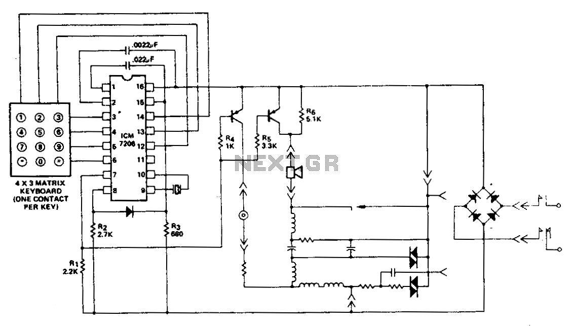
This encoder utilizes a single contact per key keyboard and manages all other switching functions electronically. A diode connected between terminals 8 and 15 limits the output to no more than 1 V negative concerning the negative supply, Vss. The circuit functions within a supply voltage range of 3.5 V to 15 V on the device side of the bridge rectifier. Transients up to 100 V will not lead to system failure; however, the encoder will not operate correctly during such conditions. Normal operation will resume immediately once the transient is eliminated. Additionally, the output voltage of the synthesized sine wave is nearly directly proportional to the supply voltage (V00 - Vss) and increases with the supply voltage between terminals 8 and 16, after which the output voltage stabilizes.
The described encoder circuit is designed to facilitate efficient switching through a single contact per key, eliminating the complexity associated with multi-contact systems. The electronic management of switching functions enhances reliability and reduces mechanical wear. The inclusion of a diode between terminals 8 and 15 serves a crucial role in protecting the circuit from negative voltage spikes, ensuring that the output does not drop below -1 V relative to the negative supply voltage, Vss. This feature is particularly important in applications where voltage transients may occur, as it helps maintain the integrity of the signal and prevents potential damage to the encoder.
Operating within a voltage range of 3.5 V to 15 V allows the encoder to be versatile and compatible with various power supply configurations. The bridge rectifier on the device side ensures that the circuit can handle AC inputs, converting them to a stable DC output needed for reliable operation. While the circuit is robust enough to withstand transients of up to 100 V, it is important to note that the encoder may not function properly during such events. However, the quick recovery time post-transient ensures minimal disruption in operation, making it suitable for dynamic environments.
Furthermore, the relationship between the output voltage of the synthesized sine wave and the supply voltage (V00 - Vss) indicates that the circuit is designed for predictable performance. The output voltage increases with the supply voltage until reaching a certain threshold, after which it stabilizes. This characteristic is beneficial in applications requiring consistent signal levels, as it allows for precise control over the output waveform. Overall, this encoder circuit represents a sophisticated solution for electronic switching, combining durability, efficiency, and ease of integration into various electronic systems.This encoder uses a single contact per key keyboard and provides all other switching functions electronically. The diode connected between terminals 8 and 15 prevents the output from goitrg more than 1 V negative with respect to the negative supply Vss.
The circuit operates overthe supply voltage range from 3.5 V1o 15 Von the device side of the bridge rectifier. Transients as high as 100 V will not cause system failure, although the encoder will not operate correctly under these conditions.
Correct operation will resume immediately after the transient is removed. The output voltage of the synthesized sine wave is almost directly proportional to the supply voltage (V00 -Vss) and will increase with the increase of supply voltage between terminals 8 and 16, after which the output voltage remains constant. 🔗 External reference