
telephone in use indicator
The described circuit is a telephone line usage indicator that operates based on the line voltage variations when a telephone handset is lifted. It utilizes two MOSFETs, Q1 and Q2, to control the state of an LED indicator (LED1) that signals whether the line is in use. The circuit is powered by the telephone line voltage, which typically remains around 48V when all phones are on-hook. The operation begins when a phone is lifted, causing a drop in line voltage. This drop changes the gate voltage of Q1, which is designed to turn off when the handset is lifted, allowing Q2 to turn on and illuminate the LED.
The design ensures minimal impact on the performance of other connected telephone devices, maintaining the integrity of the telephone line. The choice of components is critical, with specific attention to the gate-source threshold voltage of Q2, which should be suitable for the operating conditions of the circuit. The use of a 500k trimmer allows for fine-tuning the biasing of Q1, ensuring that it operates effectively under varying line conditions.
The circuit also highlights the importance of using low-current components, particularly for the LED, to prevent excessive current draw when the line is idle. The inclusion of a current-limiting resistor of at least 2.2kΩ for LED1 is essential to protect the LED from damage. Additionally, considerations for safety and legal compliance are emphasized, underscoring the need for proper expertise and awareness of local regulations regarding telephone line connections.
In summary, this telephone line usage indicator circuit offers a practical solution for monitoring line activity while ensuring compliance with safety standards and minimizing interference with existing telephone services. Proper design and component selection are vital for the effective and safe operation of this circuit.Please note that it is illegal to make a physical permanent connection to your telephone linein some countries (this includes the UK and Ireland). If building this circuit it is advisable touse a plugin cord so that the unit can be unplugged should a fault occur.
If in doubt consult either your telephone or cable operator. If all extension phones are on-hook and the line voltage is around 48V, Q1 will conduct thus effectively shorting the gate of Q2 to itssource, so it will be off and the LED will be disabled. Lifting the handset of any phone on the line causes the line voltage todrop to 5-15 V. The gate voltage of Q1, equal to some 6% of the linevoltage, will then be too low and Q1 will be turned off.
So Q2`s gateis now biased at approximately 1/2 of the line voltage, Q2 turns on andthe LED indicates that the line is in use. The circuit itself ispractically invisible to the other telephone devices using the sameline. LED1 must be low-current and its current-limiting resistor must be 2k2or more. The other components` ideal values may vary slightly, depending on the local telephone line parameters.
The circuit ispowered off the telephone line. If other types of MOSFETs are used, the 500k trimmer can be adjusted toensure that Q1 is biased fully on while the line is not in use (LED1off), and vice versa. If Q2 is not a BS108 but some other 200 V MOSFETwith a higher G-S threshold voltage, it might be necessary to increasethe value of the lower (or decrease the value of the upper) one of thetwo resistors connected to the gate of Q2.
Plain (bipolar junction) transistors can be used instead and thecircuit also works fine, but the resistor values are then much lower -letting ten times more microamps of current pass through while the lineis not in use, and even this MOSFET design still could not meet formalminimum on-hook DC resistance specifications. Both prototypes` PCBs were 4x1 cm. The current-limiting resistor forLED1 is 2k2 in both cases. DO NOT ground any of the leads or conductingsurfaces in this circuit. A more reliable design would also includesome kind of over-voltage protection etc. In their normal course of operation, telephone lines can deliverlife-threatening voltages! Do not attempt to build any of thecircuits/projects unless you have the expertise, skill andconcentration that will help you avoid an injury.
There are also legal aspects and consequences of connecting things to telephone lines, which vary from country to country. Keep away from telephone lines during a lightning storm! 🔗 External reference
Related Circuits
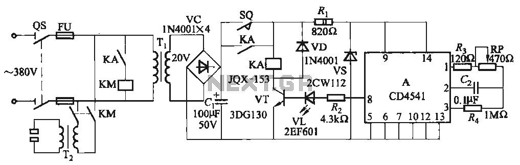
One Foot Spot Welder circuit. The circuit utilizes the IC CD4541 to provide precise delay characteristics, enabling the electrical time constant necessary for effective welding. This ensures consistent welding quality across identical weldments. For varying weldments, the electrical locator...

A repertory dialer phone contains a library of phone numbers that can be entered and dialed, allowing access to up to fifteen frequently used numbers. It also includes the capability to store the last dialed number or an additional...
Currently, there is a growing trend to utilize telephone lines for long-range control and alarm systems within transmission mediums, which is accompanied by extensive research. Such systems typically consist of alarm devices and police notification arrangements, including a central...
The circuit is designed for individuals who spend extensive hours exploring the various resources of this site. Although it comprises only three components, it effectively indicates whether the telephone line has been released after a prolonged connection via modem...
Nearly all modern computers are equipped with logic blocks that facilitate the implementation of a USB port. A USB port can deliver over 100 mA of continuous current at 5V to peripherals connected to the bus. Therefore, it serves...
Typically, a single telephone is connected to a telephone line. If an additional telephone is needed at a distance, a parallel line is installed for connecting the second telephone. This straightforward parallel line arrangement presents issues such as loss...