
Telephone Message Taker

The circuit utilizes the ringing voltage, typically around 90V AC, present on the telephone line when a call is incoming. A transformer is often employed to step down this voltage to a safer level suitable for triggering the recording device. The primary winding of the transformer is connected to the telephone line, while the secondary winding provides a lower AC voltage output.
A rectifier circuit is integrated to convert the AC voltage from the transformer into a DC voltage. This DC output can then be used to activate a relay or transistor switch, which in turn controls the tape recorder. The relay provides isolation from the high voltage of the telephone line and allows the circuit to operate safely.
In scenarios where the tape recorder requires a constant-contact closure to remain in recording mode, additional contacts can be employed. These contacts can be configured to latch the relay in an active state, ensuring that the tape recorder continues recording until the call is terminated or the circuit is manually reset. This latching mechanism can be achieved using a simple feedback loop or a flip-flop circuit, depending on the complexity required.
To ensure the circuit operates reliably, it is important to include protective components such as diodes to prevent back EMF from damaging the circuit when the relay is deactivated. Additionally, capacitors may be used to filter any noise from the power supply, ensuring clean operation of the tape recorder. Proper component ratings should be considered to handle the expected voltage and current levels throughout the circuit. This circuit operates on the ringing voltage of the telephone to trigger a tape recorder to record messages. Kl can be made to latch using extra contacts if the tape recorder requires a constant-contact closure.
Related Circuits
It is a relatively simple circuit, with which we can have optical and sound clue, when we have telephone ring in the line of telephone. The calls in the line, are changed in pulses of frequency 400 HZ from...
During a telephone conversation with a distant subscriber, it is common to experience frustration due to the faintness of the voice, making it difficult to understand. To address this issue, a circuit for an inexpensive amplifier is presented. This...
This Project is used to control our household electrical devices from anywhere through the cell phone. The circuit consists of a DTMF tone detector and a powerful 8-bit Microcontroller AT89S52. The microcontroller controls all the system. In this project,...
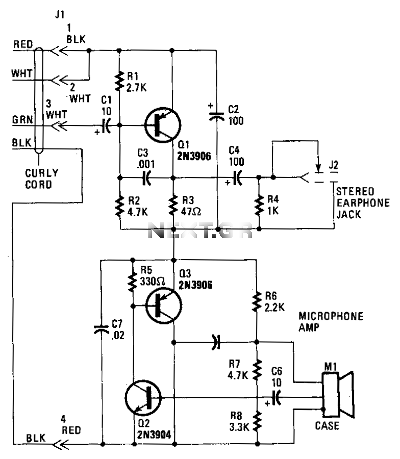
Transistor Q1 in the headset amplifier circuit amplifies the 30 mV signal intended for the earphones to 0.5 V, which is sufficient to drive stereo earphones. Capacitor C1 blocks any DC current from shorting back into the telephone base....
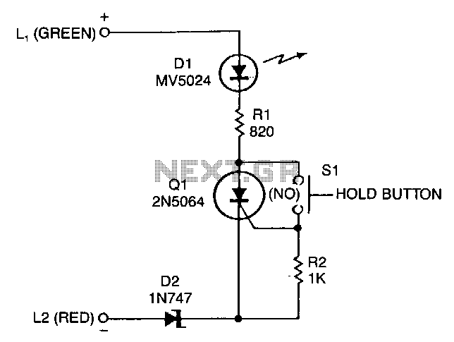
A sensitive-gate SCR provides a line-holding current of 20 to 40 mA, depending on loop resistance. It also lights an LED to give the user a positive indication that the telephone line is on hold. The 20 to 40...
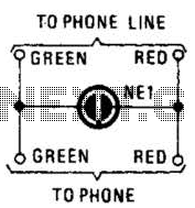
A neon lamp can easily be added to the phone line to act as a ring indicator. It is perfect for times when you cannot hear the phone. The integration of a neon lamp as a ring indicator in a...