
Temperature Controlled NICD Charger

The described circuit functions as a temperature-controlled constant current battery charger, specifically designed for nickel-cadmium (NiCd), nickel-metal hydride (NiMH), and similar rechargeable battery types. The fundamental operation relies on the thermal response of the batteries; as they reach full charge, their internal temperature rises, which is monitored to prevent overcharging—a significant factor in prolonging battery life.
The initial power stage of the circuit includes a transformer that steps down the AC mains voltage to a lower AC voltage suitable for charging. Following this, a bridge rectifier converts the AC voltage to pulsating DC, which is then smoothed by a 1000µF capacitor, resulting in approximately 22V of DC power. This voltage is necessary to ensure that the subsequent components in the circuit receive adequate power.
To regulate this voltage, a 7812 voltage regulator is employed, which steps down the voltage to a stable 12V. This regulated output is crucial for the operation of the LM311 voltage comparator and the 4011 NAND gates that are integral to the control logic of the charger. The LM311 comparator serves to monitor the voltage across the battery, while the NAND gates are used to implement the control logic that manages the charging process.
The circuit is initiated by pressing a start switch, which activates the charging sequence. This switch connects the power supply to the charging circuitry, allowing the charger to begin monitoring the battery's voltage and temperature. The control logic ensures that the charging current remains constant until the battery temperature indicates it is fully charged, at which point the charging process is halted to prevent damage from overcharging.
In summary, this temperature-controlled constant current battery charger is a vital circuit designed to safely charge rechargeable batteries while monitoring their thermal characteristics to prevent overcharging and extend battery life. The combination of a transformer, rectifier, smoothing capacitor, voltage regulator, comparator, and logic gates creates a robust and efficient charging solution.This circuit is for a temperature controlled constant current battery charger. It works with NICD, NIMH, and other rechargeable cells. The circuit works on the principle that most rechargeable batteries show an increase in temperature when the cells becomes fully charged. Overcharging is one of the main causes of short cell life, hot cells pop their internal seals and vent out electrolyte.
As cells dry out, they lose capacity. The transformer, bridge rectifier, and 1000uF capacitor provide around 22 Volts of DC power to run the rest of the circuit. The 7812 regulator drops this to 12V to run the 311 comparator and 4011 nand gates. The start switch is pressed to start the cha 🔗 External reference
Related Circuits
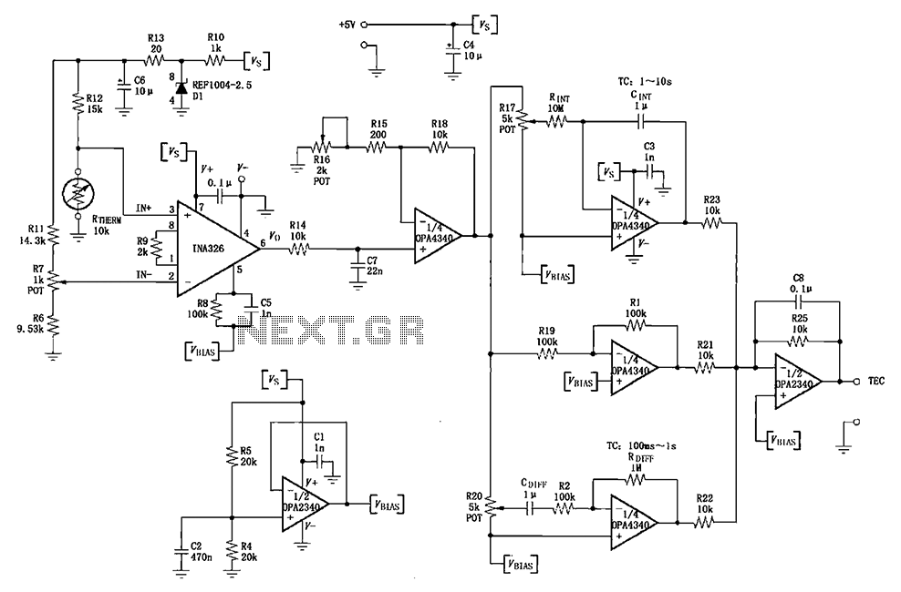
The INA326/327 forms a single power PID (proportional-integral-derivative) controller as illustrated in the temperature control loop. This circuit is primarily designed for temperature measurement and control. A thermistor, designated as RTHERM, detects temperature changes and converts them into an...
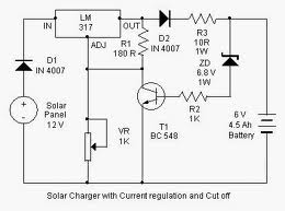
By adjusting the Adjust pin, the output voltage and current can be regulated. A variable resistor (VR) is connected between the Adjust pin and ground to achieve an output voltage of 9 volts to the battery. Resistor R3 limits...
This circuit diagram represents a radio-controlled system, commonly used in toy car applications for children. The circuit consists of two main parts: the transmitter and the receiver. The transmitter generates radio signals using an oscillator circuit formed by transistor...
The circuit is designed for temperature control using a fan. It can regulate temperature and also provides temperature indication. All the functions mentioned are monitored. The temperature control circuit utilizes a fan to maintain a desired ambient temperature within a...
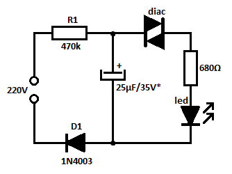
This is likely the simplest concept for generating a flashing light from an LED using alternating current (AC). The circuit provides a straightforward method for flashing one or more LEDs using high-voltage direct current (DC) sourced from mains electricity....
A more affordable method to create or purchase a device that offers similar functionality. It does not necessarily need to be remote-controlled if it can be programmed to activate at specific times. This description suggests the development of a cost-effective...