Test-Measurement 4

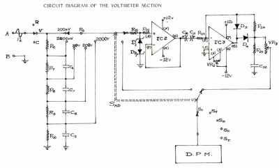
In circuit diagrams provided in equipment manuals, voltages at various points in the circuit are typically indicated. A deviation from these specified values suggests that a component has failed and can help in identifying faulty areas. Specifications include: D.C. Voltage Ranges: +/- 200 mV, 2V, 20V, 200V, 2000V. Input impedance is 10 megaohms. Additional specifications include circuit protection up to +2000V D.C. across all ranges, an over range indication of 100% to 1999, and an accuracy of +/- 0.5%. The A.C. voltage note indicates average responding ranges that are calibrated. This circuit was intended to be a portable, low-cost insulation tester for electricians. A negative voltage is generated by shifting ground with two diodes, although this approach may not have functioned effectively. Two pins of the CD4028 are utilized to enhance the reference voltage to achieve two additional ranges, as the CD4051 has a 100-ohm resistance. The design aims to create a single-digit voltmeter that can measure from +0 to +9V DC with an error margin of +/- 1V. This circuit also facilitates monitoring of mains supply voltage without using an isolation step-down transformer, and it should only be constructed by individuals with safety knowledge. Capacitor C1 limits current and drops most of the voltage, while a zener-regulated supply powers the chip. Capacitor C2 can be increased to 220uF or more if necessary, as the bar mode display may consume additional power. Resistors R2, R3, R5, and R6 form a voltage divider to sample the input voltage, and D11 with capacitor C3 provide the DC value. The preset resistor R5 can be adjusted with a plastic tweaker to calibrate the fifth LED.
The circuit described serves multiple functions, primarily focusing on voltage measurement and insulation testing. The inclusion of various D.C. voltage ranges allows for versatile applications, making it suitable for different testing scenarios encountered by electricians. The high input impedance of 10 megaohms ensures minimal loading on the circuit under test, preserving the integrity of the voltage readings.
For circuit protection, the design accommodates voltages up to +2000V D.C., safeguarding the components and the user. The over range feature, which indicates readings from 100% to 1999, provides a clear indication when the input voltage exceeds the maximum measurable limit, alerting users to potential issues.
The negative voltage generation through ground shifting with diodes indicates a creative approach to extend the measurement range. However, the effectiveness of this method may require further evaluation and testing to ensure reliability.
The use of the CD4028 and CD4051 integrated circuits enhances the functionality of the circuit by allowing for additional voltage range selections. These components are crucial in managing the reference voltage levels, which is essential for accurate measurements.
The design's emphasis on safety, particularly in the mains voltage monitoring application, highlights the importance of proper construction and knowledge of electrical safety standards. The circuit's reliance on capacitors and resistors to manage voltage levels and current flow demonstrates a fundamental understanding of electronic principles.
In summary, this circuit is a well-thought-out design aimed at providing a portable, cost-effective solution for insulation testing and voltage measurement. With careful calibration and testing, it has the potential to be a valuable tool for electricians.In circuit diagrams given in equipment manuals, voltages at various points in the circuit are usually marked. A deviation from these values indicates that some component has failed and eventually leads to clues for isolating the faulty areas.
Specifications :- D. C. Voltage Ranges : +/- 200 mV, 2V, 20V, 200V, 2000V. Input impedance: 10 mega ohms. Circuit protection: + 2000V D. C. all ranges. Over range: 100% to 1999. Accuracy: +/- 0. 5%. A. C. Voltage Note: Average responding Ranges calibrated Read More I don`t remember if this circuit worked properly. But a few were made and i might not have shown the modifications that were done to make it work. This was meant to be a portable, low cost, insulation tester for an electrician. If you try it out and debug it it may work well. A negative voltage is derived by shifting gnd with two diodes, i feel this did not work very well. Two pins of CD4028 pins are also used to boost the reference to get two extra ranges as 4051 has a 100E on resistance.
From Schematics of Read More I wanted to design a logic probe as a tutorial, but there were many good ones in the web so i have tried to design a single digit voltmeter. This circuit is a design, i am unable to test it now, later if i test it and find mistakes i will update this page.
You can help me by pointing out the errors. First bear it in mind that it is a single digit voltmeter which is 0-9 counts only on the positive side, that is it can measure +0 to +9V DC +/- 1V error. That may not be Read More This Circuit helps in the monitoring of mains supply voltage. It does not use a isolation step down transformer. This has to be constructed only by skilled people with knowledge of safety requirements. C1 limits the current and drops most of the voltage. The zener regulated supply is for the chip. C2 can be raised to 220uF or more if required. The bar mode display may consume more power. R2-R3-R5-R6 form a voltage divider to get a sample of the input voltage, D11-C3 get the DC value. Adjust R5 preset with a log Plastic tweaker to get the 5th led Read More 🔗 External reference
