
The Accelerometer Circuit

The schematic consists of the following key components: the ADXL320 accelerometer, the PIC microcontroller, and an LED indicator. The ADXL320 sensor is a three-axis accelerometer capable of providing analog output signals corresponding to acceleration along the X, Y, and Z axes. The output signals are fed into the PIC's A/D converter inputs.
The PIC microcontroller is programmed to continuously sample the analog voltage signals from the ADXL320. The software will convert these analog values into digital representations that correspond to the acceleration forces acting on the sensor. By analyzing these values, the microcontroller determines the tilt angle or the rate of acceleration.
The LED is connected to one of the output pins of the PIC. The blinking frequency of the LED is modulated based on the processed acceleration data. For instance, a higher acceleration detected by the ADXL320 will result in a faster blinking rate of the LED, while lower acceleration will cause a slower blink. This visual feedback provides an intuitive way to observe the sensor's response to motion.
The power supply circuitry must ensure that the PIC receives a stable +5V supply. This can be achieved using a simple battery configuration or a more complex power management circuit, depending on the application requirements. Proper decoupling capacitors should be included near the power pins of the PIC and ADXL320 to filter any noise and ensure stable operation.
Overall, this circuit provides a basic yet effective demonstration of interfacing an accelerometer with a microcontroller, showcasing how sensor data can be processed and represented visually through an LED indicator.The schematic is very simple for this tutorial. It is just a matter of wiring up the ADXL320 sensor to the PIC and the LED. The power circuitry assumes you have a battery of +5v to power the PIC. You can create your own custom circuitry for this or just use a battery array. whatever you like. The PIC is the brains of the circuit. Using the A/D`s on the PIC data samples will be taken as input and then evaluated. Based off different inputs the LEDs will blink faster or slower to show how much the board has been tilted or accelerated. This sensor will output an analog signal to the PIC to be interpreted. The signal is measured by its change in voltage when you want to find out how many g`s are currently being `pulled`.
This is just one single LED added to the circuit. Depending on how fast it is blink will tell us how much acceleration or tilt is being applied to the ADXL320 sensor. This will of course all be done in software in the PIC. 🔗 External reference
Related Circuits
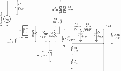
It employs a low threshold MOSFET and two coupled coils to function as a joule thief. An additional MOSFET is utilized for regulation. The circuit operates as a joule thief, which is a type of DC-DC converter designed to extract...
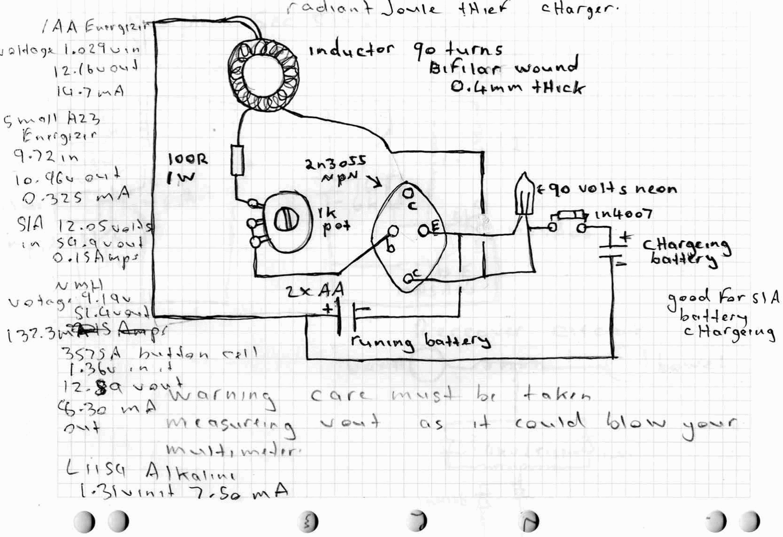
A high power joule thief circuit is explained in this post, which can be constructed by any new hobbyist. Here is the simplified drawing of the radiant joule thief battery charger. The inductor was wound with many turns until...
It is easy to miss the sound of a doorbell while watching TV. This circuit addresses the issue by providing a visual indication, such as a lamp or an LED. Connecting a lamp directly in parallel with the doorbell...
It is a wireless doorbell with a cost of about $10.00. This product encourages a shift in approach to building projects, utilizing such items to learn about their functions and modify them to meet specific needs. The doorbell incorporates...
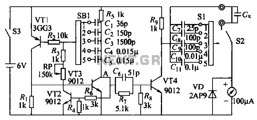
A capacitive measuring instrument is a direct reading device that measures the capacitance of a circuit. This instrument is capable of measuring capacitance values ranging from a few picofarads to 0.1 microfarads, with specific ranges of 25 pF, 100...
The induction coil detects the magnetic field flux during phone calls, amplifies the signal, and triggers the LED. These circuits are designed for the phone to rest on the pickup coil. The electromotive force (emf) from the bell electromagnets...
Warning: include(partials/cookie-banner.php): Failed to open stream: Permission denied in /var/www/html/nextgr/view-circuit.php on line 713
Warning: include(): Failed opening 'partials/cookie-banner.php' for inclusion (include_path='.:/usr/share/php') in /var/www/html/nextgr/view-circuit.php on line 713