
The Active High Pass Filter
Active high-pass filters are essential components in electronic circuits, designed to allow signals with frequencies higher than a certain cutoff frequency to pass while attenuating signals with lower frequencies. The primary function of these filters is to enhance signal integrity in applications such as audio processing, communications, and instrumentation.
The frequency response of an active high-pass filter is characterized by its cutoff frequency, which is determined by the values of resistors and capacitors used in the circuit. The cutoff frequency (fc) can be calculated using the formula:
fc = 1 / (2πRC)
where R is the resistance and C is the capacitance. Above this frequency, the output signal is significantly amplified, while below it, the signal is increasingly attenuated.
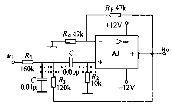
Op-amp voltage gain is a critical aspect of active high-pass filters. The gain can be adjusted by selecting the appropriate feedback and input resistor values in the op-amp circuit configuration. The gain (A) can be expressed as:
A = Vout / Vin = (Rf / Rin) + 1
where Rf is the feedback resistor and Rin is the input resistor. This gain allows for the amplification of the desired high-frequency signals while suppressing unwanted low-frequency noise.
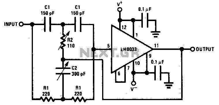
The construction of an active high-pass filter typically involves operational amplifiers (op-amps), resistors, and capacitors. A common configuration is the Sallen-Key topology, which provides a simple and effective means to implement the filter. In this configuration, the op-amp is used in a non-inverting mode, with the resistive and capacitive components determining the filter's characteristics.
When designing an active high-pass filter, it is essential to consider factors such as component tolerances, power supply requirements, and the specific application needs to ensure optimal performance. Proper simulation and testing of the circuit can further validate its functionality and reliability in real-world applications.Electronics Tutorial about Active High Pass Filter including its High Pass Filter Frequency Response, Op-amp Voltage Gain and Active Filter Construction.. 🔗 External reference
Related Circuits

The Wildcard requires a minimum of 8 volts on the V+Raw power rail, which must not exceed 26 volts. When using the Docking Panel or Power Dock, the V+Raw rail is automatically connected. If not using a dock, manual...
The figures below illustrate using opamps as active 2nd order filters. Three 2nd order filters are shown, low pass, high pass, and bandpass. Each of these filters will attenuate frequencies outside their passband at a rate of 12dB per...
Component value sensitivity is extremely critical, as are temperature coefficients and matching of the components. Best performance is attained when perfectly matched components are used and when the gain of the amplifier is unity. To illustrate, the quality factor...

A step-up converter can be designed using the MAX641 integrated circuit from Maxim IC, utilizing a minimal number of electronic components. This high-voltage step-up converter project can deliver a maximum output current of up to 1A. The low battery...
A band-pass filter permits only signals within a specified frequency range to pass through, while attenuating or suppressing those outside this range. This is characterized by a lower frequency limit and an upper frequency limit. A typical implementation is...
This circuit incorporates a datasheet-compliant trigger signal, reversed polarity protection, an optional test button, and the capability for battery operation. It utilizes either the U1 L601E3 or MAC97A8 triac, rated for 400 V and 1 A. When U1 is...