
The Autonomous Drifter Circuit

The RC car transmitter circuit is a fundamental example of combining digital and analog components to achieve wireless control. The two halves of the circuit serve distinct yet complementary roles, with the left side focusing on digital signal processing. The pressing of switches 1-4 activates IC1, which encodes the user input into a PWM signal. This encoding is essential for ensuring that the transmitter can communicate effectively with the receiver in the RC car.
The choice of power supply is also notable; while the design originally calls for a 9V battery, the use of a +5V supply from an LM7805 voltage regulator demonstrates a practical approach to circuit design, allowing for lower power consumption while maintaining functionality. This decision reflects a common practice in electronics where efficiency and simplicity are prioritized.
The switches' connection to ground is a critical aspect of the circuit operation. When a switch is pressed, it completes the circuit to ground, signaling to the microcontroller the desired action. This connection allows for real-time control of the car's movements, emphasizing the importance of understanding how user inputs translate into electrical signals.
The 27MHz oscillator (X1) plays a pivotal role in frequency modulation. This oscillator generates a stable frequency that is necessary for the RF transmission. The output signal, modulated by this frequency, is then processed through R4, which likely serves as a filtering component to ensure that only the desired frequency components are passed to the output transistor (TR1). The transistor amplifies the signal, allowing it to be transmitted over a distance.
The low power output indicates that the circuit is designed for efficiency, suitable for battery-operated devices like RC cars. The speculation surrounding IC1 highlights the challenges often faced in reverse-engineering circuits, particularly when components are obscured. Nevertheless, the function of IC1 as a PWM encoder is crucial for the operation of the transmitter. The ability to switch encoding modes via a 3-way switch illustrates a thoughtful design choice, enabling multiple vehicles to be controlled without interference, showcasing the ingenuity behind the circuit's design.The first schematic that we`ll look at is the base schematic of the transmitter without any modification. The RC car`s transmitter circuit has two halves to it. One side (on the left) is pretty much all digital. When a switch(1-4) is pressed, IC1 becomes active and an encoded PWM (pulse with modulation) signal is output.
The packaging for the tr ansmitter required a 9v battery to be used. Since we`re wise in the ways of circuits and see that this circuit can operate as long as the IC has enough power to function, we`ll just use +5v off the LM7805. These switches control what the car does. Move forward, backward, left or right. Look carefully at where the switches are connected to ground. When the switch is pressed ground is connected. These are the key spots to making the microcontroller able to control what the transmitter outputs. We`ll see what connects to them on the next schematic. The crystal labeled X1 is actually a 27MHz oscillator. This will generate the frequency signal that the IC1 output will be modulated to (Toy RC cars are allowed to be on either 27MHz or 49 MHz frequency channels).
The signal mixing occurs directly after the R4 Resistor approaching the output transistor (TR1). Output finally occurs after all that and is relatively low power (mW range). Understanding this circuit is not crucial to creating this project. Just a small note. IC1 is unknown. What exactly it is, is not directly clear as there is a nice glab of black crap right over it. My best guess is it is either a microcontroller or encoder as it outputs an encoded PWM signal to be modulated. If you switch the 3-way switch on the transmitter the encoding changes (this is to allow 3 cars to be able to be controlled simultaneously).
🔗 External reference
Related Circuits
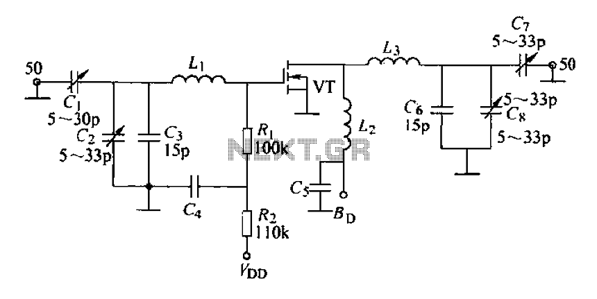
A 175 MHz high-frequency amplifier circuit utilizing a field-effect transistor (FET) is presented. The field-effect transistor used is the 3D04H, along with its associated components and parameters. The 175 MHz high-frequency amplifier circuit is designed to amplify signals in the...
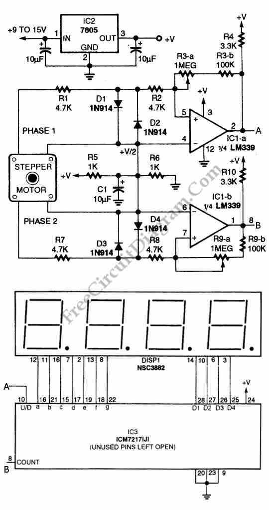
The circuit illustrated in the schematic diagram below allows for the visualization of the direction and shaft rotation of a stepper motor on an LED display. Instead of employing a digital rotation encoder as an input, this circuit utilizes...
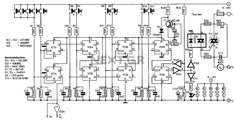
This switch utilizes four CD4013BE dual flip-flops, an inverter, and an optoisolator to control a triac, allowing it to switch a 25-A AC load current. A standard 4x3 telephone keypad is employed for entering a 6-digit code. In the...

Having reliable connections is essential not only in daily life but also in electronics. Unlike social connections, the dependability of electrical contacts is crucial for the proper functioning of electronic devices. In the realm of electronics, the integrity of electrical...
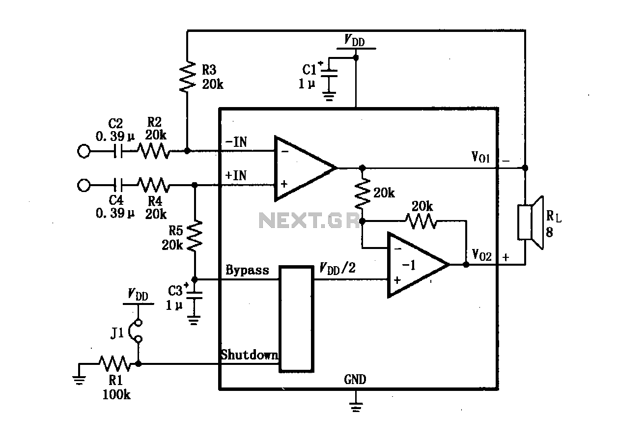
The LM4904 audio input differential amplifier circuit is presented. The audio signal is provided as a differential input to the +IN and -IN terminals. The LM4904 is a low-power audio input differential amplifier designed for high-performance audio applications. This circuit...
Only one channel of this circuit is shown. The other is practically identical. The input to the circuit, taken from the speaker output of a car radio, is divided into two paths. In one path, a high-power divider network...