
The brake a little dynamic braking circuit
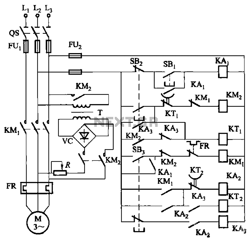
The circuit operates through a combination of relays and buttons that control the braking process effectively. The start button (SBz) initiates the motor operation, while the stop button (SBz) halts it. The jog button (SB3) allows for momentary operation of the motor, facilitating precise control during tasks that require brief bursts of movement.
The adjustable relay KTi defines the normal braking time, ensuring that the motor comes to a stop within a predetermined duration, enhancing safety and operational efficiency. The timing adjustments for both KTi and KTz provide flexibility in the braking response, accommodating different operational requirements based on load conditions or specific application needs.
In the jog mode, the circuit exhibits a sophisticated control mechanism. If the jog operation is performed with intervals shorter than the specified tuning time of KTz, the braking system remains engaged, allowing for rapid successive jogs without fully disengaging the brake. This feature is particularly useful in applications where precise positioning or repetitive movements are required.
Conversely, if the interval exceeds the set threshold, the system automatically transitions to a safe state by disconnecting the relay KAz and KA3, which in turn disengages the contactor KM2. This ensures that the motor is completely released from the braking action, preventing potential mechanical stress or overheating from prolonged braking engagement.
Overall, the circuit design provides a robust solution for motor control, effectively balancing between operational flexibility and safety through adjustable timing parameters and strategic relay configurations. Circuit shown in Figure 3-143. The line not only make the braking effect of the motor is in the normal shutdown, and jog through the process and has a good braking effect. Figu re, SBz the start button, SBz the stop button, SB3 jog button. Normal braking time by the time the decision relay KTi (3-4s, adjustable). When the jog control, if the time interval of less than two jog KTz tuning time (2 ~ 3s, adjustable), the delay does not turn off normally closed contact, then press the SB3 is jogging, pine SB3 that is open to the brake; if the interval is greater than twice jog KT2 tuning time, or jog end, KTz normally closed contacts disconnect timer, relay KAz, KA3 has lost power release, KA3 normally open contact disconnect and contactor KM2 missing, and released end braking.
Related Circuits
The provided schematic diagram illustrates an LM741 light/dark sensor circuit, derived from the 741 Op-Amp Tutorial by Tony van Roon. The ECG128/NTE128 transistor can be replaced with any NPN transistor that meets the necessary gain and current specifications for...
If the offset value exceeds 5mV, adjust this value by experimenting with resistors, starting with 220K, connected from test point Z (the junction of R22 and R23) to +V if there is a negative voltage, or to -V if...
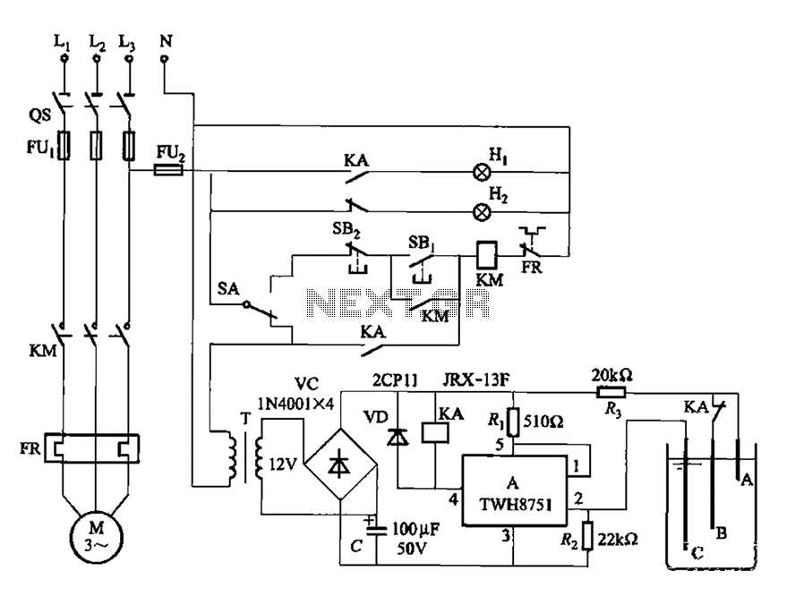
The power switch integrated circuit A features a straightforward design with high sensitivity, ensuring reliable operation. It is part of an automatic liquid level control circuit. When the water level at electrode B drops below 2 feet (0V), circuit...

Phase noise is a critical performance parameter of frequency synthesizers for wireless applications. RF system designers of phase-modulated cellular systems, such as PHS, GSM, and IS-54, require low noise local oscillator (L.O.) or frequency synthesizer blocks. This document describes...
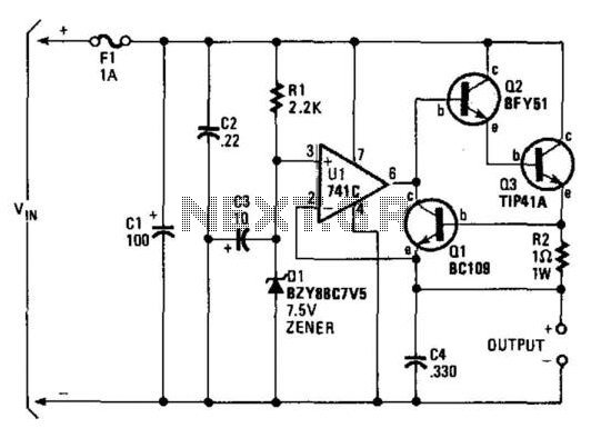
A regulator enables the powering of a 7.5-V cassette recorder or other devices from a 12-V DC automotive system. The circuit can provide approximately 600 mA of current. Q3 requires a heatsink due to its potential to dissipate up...
The crystal radio derives its name from the galena crystal (lead sulfide) utilized for rectifying signals. A "cat's whisker" wire contact was adjusted on the crystal's surface until a diode junction was established. The 1N34A germanium diode serves as...