
The contact resistance measuring circuit
The contact resistance measuring circuit is designed to provide accurate measurements of low resistance values by utilizing a constant current source and an operational amplifier-based amplification method. The key components include a constant current circuit that ensures a steady current flows through the resistance being measured, which is essential for reliable readings. The operational amplifier IC1 serves as a voltage follower, maintaining the voltage across the load equal to the reference voltage from the regulator.
The configuration of operational amplifier IC2 as an inverting amplifier allows for the amplification of the voltage difference between points A and B. The gain of this amplifier can be adjusted by selecting appropriate resistor values, specifically Rz, which plays a crucial role in determining the sensitivity and range of the measurements. The inclusion of the capacitor Cz aids in stabilizing the output voltage, ensuring that transient responses do not affect the accuracy of the readings.
The millivoltmeter connected to the output of IC2 provides a direct readout of the amplified voltage, which corresponds to the resistance being measured. The fixed output voltage Vo serves as a reference point for calibration and ensures that the measurements are consistent and repeatable. The overall design allows for precise measurement of contact resistance, making it suitable for applications in various electronic testing environments.
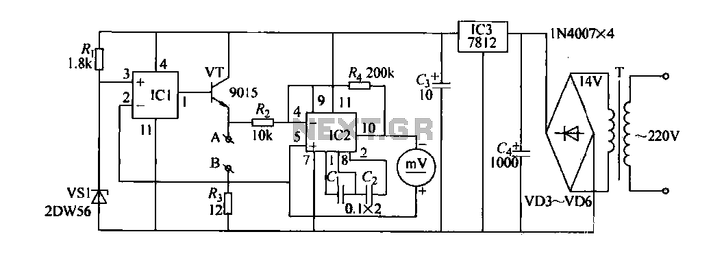
The circuit also incorporates diodes VD1 to VD6 for voltage regulation and protection, ensuring that the operational amplifiers and other sensitive components operate within their specified voltage limits. The power supply section, which provides a stable 12V output, is critical for maintaining the performance of the circuit, particularly when measuring resistances under varying load conditions. This comprehensive approach to resistance measurement enhances the reliability and accuracy of the circuit, making it an effective tool for engineers and technicians in the field.Contact resistance measuring circuit shown in FIG. It mainly consists of a constant current circuit and amplifying circuit. Operational amplifier 1C1 and form a transistor VT a follower, the voltage across the wind equals the nominal regulator VS1 steady voltage. Since the fixed resistance Ra, therefore, through Rs is a constant-current. Measured resistance string A, B-side, at the connection point with the measured resistance Ken, the current value is small, it can be measured by the resistance of the wind currents regarded as the same voltage, so that, A, B between the end and then only in the A, B-side test the resistance of the (proportional relationship). Electrical resistance measurements translate into voltage measurements. Op amp IC2 and its external RC element constituted an inverting amplifier, voltage A, B between amplification, magnification brother/Rz.
c], Cz IC2 is required memory capacitance. Millivoltmeter connected to the output terminal of IC2. Measurement IC2 output voltage. False 102 fixed output voltage Vo, the voltage magnification K., VD1 rated stable voltage Vw, the measured resistance to foot., There/Ct VwR4Rn/R3RZ R Rz Ra V/R4 Vw figure. T, VD3-VD6,1C3 other components constituting the DC power supply, AC power when using the meter, stable 12V output voltage.
Related Circuits
Some simple 555 and flip-flop circuits are being developed to add electronic lighting effects to modernize games. Various circuits are being collected for different game aspects, such as idle states, flipper shots, flower openings, winning shots, etc. A collection...
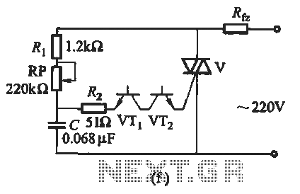
The introduction for a unidirectional thyristor trigger circuit is also applicable to the TRIAC. Various configurations are presented in Figure 16-28. Figures 16-28 (a) and (b) illustrate a direct trigger circuit; Figure 16-28 (c) depicts a dual diode trigger...

This circuit allows for the observation of movement between various stroboscopes. The generation of a rectangular signal is accomplished using an NE555 timer. The circuit operates with a low power supply, which is constructed from a simple transformer (TR1),...
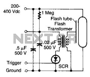
This circuit is beneficial for applications requiring a low-energy flashing alarm. A DC supply ranging from 200 to 400 volts should possess sufficient internal resistance to charge a 0.5 microfarad capacitor between flashes. This charging process should take approximately...
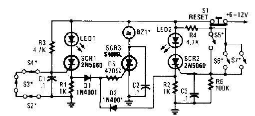
A straightforward high-power alarm driver electronic project can be developed using this circuit diagram. This high-power alarm driver project utilizes a low-power SCR to trigger a high-power SCR. When switches S2, S3, or S4 are opened or switches S5,...

This jammer circuit can be utilized both indoors and outdoors, providing a coverage range of approximately 30 meters to disconnect wireless devices from their communication with the base station. The circuit design employs frequency ranges allocated to mobile operators,...
Warning: include(partials/cookie-banner.php): Failed to open stream: Permission denied in /var/www/html/nextgr/view-circuit.php on line 713
Warning: include(): Failed opening 'partials/cookie-banner.php' for inclusion (include_path='.:/usr/share/php') in /var/www/html/nextgr/view-circuit.php on line 713