
The Crystalizer
A classic amateur radio transmitter topology, known as the oscillator-amplifier (often referred to as master oscillator, power amplifier, or MOPA), utilizes one tube for frequency control and another for RF power amplification. In its quartz-crystal-controlled form, it typically allows operation on two or more bands with a single crystal. Frequency multiplication, which involves generating and selecting harmonics (multiples) of the crystal oscillator's fundamental frequency, serves as the basis for this design. In the early days of frequency multiplication, separate stages were required for the frequency generator and harmonic multiplier due to the limited availability of triode vacuum tubes. The introduction of the screen-grid tube (including tetrodes, pentodes, and beyond) allowed for the integration of a triode oscillator at the crystal fundamental frequency while achieving harmonic output through appropriate tuning of the plate. This innovation made it feasible to create two-tube, three- and four-band oscillator-amplifier transmitters by 1933 CE. Most screen-grid oscillators capable of this operation are a form of tri-tet, although non-tri-tet variations, such as Frank Jones's harmonic Pierce oscillator, were also developed. Efforts to replicate the functionality of the tri-tet multiband oscillator using transistors led to successful results in synthesizing a tetrode with cascode-connected vacuum-tube triodes for regenerative-detector applications. The concept of a cascoded-BJT voltage-controlled oscillator (VCO) buffer amplifier, as described by David Stockton, GM4ZNX, in the ARRL Handbook for Radio Amateurs, prompted exploration into whether an oscillator based on cascoded transistors could achieve similar multiband capabilities. Wes Hayward, W7ZOI, noted that the Experimental Methods in RF Design (EMRFD) included a cascoded-BJTs variable crystal oscillator (VXO) first introduced by Rick Campbell, KK7B, in "The MicroT2 – A Compact Single-Band SSB Transmitter," published in QST in December 2006. Campbell's design aimed for highly stable output at the crystal fundamental frequency, which was achieved using a low-pass pi network to suppress harmonics. This topology was further examined for its ability to provide useful output at the second harmonic. The resulting circuit (Figure 1) not only produces output at the fundamental frequency and its second harmonic but also at subharmonics ranging from f/2 to f/6 through the gated-LC-oscillator technique described in J. A. De Young's "A Frequency-Lock Multi-Vider," published in QST in September 1935. Figure 3 illustrates the amplifier circuit used to elevate the Crystalizer output to a level suitable for driving a vacuum-tube-based crystal oscillator stage. The Crystalizer operates using two bipolar junction transistor cascode oscillators (BCOs) and provides output at either the crystal fundamental or a harmonic when switch S1 is set to X, with tuned circuit L2-C2 selecting the appropriate frequency. When S1 is switched to L, output at subharmonics of the crystal fundamental is available with tuned circuit L1-C1 adjusted accordingly. (L2 is 6.6 µH and L3 is 1 µH for output at 3.5 MHz; scaling is required for other bands.) The CTRL terminal can be grounded or ungrounded to turn the Crystalizer on and off for spotting and transmit-receive switching purposes. When amateur radio station W9VES operates at 3.56 MHz under crystal frequency control, the Crystalizer generates the driving signal from a 7.12-MHz crystal. For its frequency-division function, the Crystalizer employs the BJT equivalent of the frequency-locking technique implemented in the "Frequency-Lock Multi-Vider" circuit. The design also incorporates the 46 dual-grid power amplifier tube, which is suitable for use as a low- or high-µ triode, functioning as a tetrode in this application.
The oscillator-amplifier topology described serves as an efficient means of generating multiple frequencies from a single crystal oscillator. The use of cascoded BJTs enhances the stability and performance of the oscillator, allowing for precise control over the output frequencies. The integration of subharmonic outputs expands the versatility of the transmitter, enabling operation across various amateur radio bands with minimal component changes. This adaptability is particularly beneficial for amateur radio operators seeking to optimize their equipment for different communication scenarios. The design principles and techniques outlined in the original description reflect a significant advancement in radio transmitter technology, demonstrating the evolution from vacuum tube-based systems to modern transistor-based solutions. The careful selection of components, such as the dual-grid power amplifier tube, underscores the importance of achieving both power efficiency and signal integrity in RF applications. Overall, this circuit exemplifies the ingenuity and resourcefulness of amateur radio engineers in pushing the boundaries of frequency generation and amplification.A classic amateur radio transmitter topology, the oscillator-amplifier (sometimes called master oscillator, power amplifier, or MOPA), used one tube for frequency control and another for RF power amplification, and in quartz-crystal-controlled form commonly allowed operation on two or more bands with one crystal. Frequency multiplication ”generat ion and selection of harmonics (multiples) of the crystal oscillator`s fundamental frequency ”was the basis for this. In the earlier days of frequency multiplication, separate stages performed the roles of frequency generator and harmonic multiplier because only triode vacuum tubes were available.
The advent of the screen-grid tube (tetrodes, pentodes, and beyond), the embedded screen grid/control grid/cathode triode in which could serve as a triode oscillator at the crystal fundamental while harmonic output was obtained by suitably tuning the plate, made two-tube, three- and four-band oscillator-amplifier transmitters possible by 1933 CE. Nearly all screen-grid oscillators capable of this class of operation are a form of tri-tet, although non-tri-tet variations, such as Frank Jones`s harmonic Pierce oscillator, were possible as well.
Seeking to approach the utility of the tri-tet multiband oscillator with transistors, and having achieved excellent results in synthesizing a tetrode with cascode-connected vacuum-tube triodes for regenerative-detector service, I recalled the cascoded-BJTs VCO buffer amplifier described by David Stockton, GM4ZNX, in the Oscillators and Frequency Synthesizers chapter he wrote for the 1995 CE ARRL Handbook for Radio Amateurs and wondered if an oscillator based on cascoded transistors might approach the multiband utility of the tri-tet. Through private correspondence, Wes Hayward, W7ZOI, pointed out that Experimental Methods in RF Design (EMRFD) had included in its Figure 12.
47 the cascoded-BJTs variable crystal oscillator (VXO) first described by EMRFD co-author Rick Campbell, KK7B, in "The MicroT2 ”A Compact Single-Band SSB Transmitter, " QST, December 2006, pages 28 33. Rick`s goal in developing that design had been highly stable output at the crystal fundamental; its output was obtained through a low-pass pi network that suppressed harmonics.
Could that same general topology provide useful output at the second harmonic Yes ”and the circuit I arrived at (Figure 1), does more: It produces output not only at f and 2f, but also at f/2 through f/6 using the gated-LC-oscillator technique (Figure 2) described in J. A. De Young, W1HHW, "A Frequency-Lock Multi-Vider, " QST, September 1935 CE, pages 32 and 33. Figure 3 shows the amplifier circuit I use to bring the Crystalizer output up to a level suitable for driving a vacuum-tube-based crystal oscillator stage.
Figure 1 ”Operating by means of two bipolar junction transistor cascode oscillators (BCOs), this circuit, the Crystalizer, provides output at the crystal fundamental or a harmonic when S1 is set to X, with tuned circuit L2-C2 selecting the appropriate frequency. Output at submultiples (subharmonics) of the crystal fundamental is available when S1 is set to L and tuned circuit L1-C1 is tuned to the appropriate subharmonic.
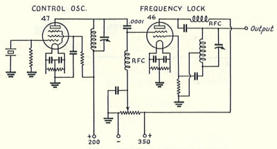
(L2 is 6. 6 µH and L3 is 1 µH for output at 3. 5 MHz; scale for other bands. ) Grounding and ungrounding the CTRL terminal turns the Crystalizer on and off for spotting and transmit-receive-switching purposes. When amateur radio station W9VES operates at 3. 56 MHz under crystal frequency control, the Crystalizer generates the driving signal ”from a 7. 12-MHz crystal. Figure 2 ”For its frequency-division function, the Crystalizer uses the BJT equivalent of the frequency-locking technique implemented in this circuit, the "Frequency-Lock Multi-Vider" (J.
A. De Young, W1HHW, QST, September 1935 CE, pages 32 and 33). Note the use of the 46 dual-grid power amplifier tube ”designed for use as a low- or high- µ triode ”as a tetrode 🔗 External reference
The oscillator-amplifier topology described serves as an efficient means of generating multiple frequencies from a single crystal oscillator. The use of cascoded BJTs enhances the stability and performance of the oscillator, allowing for precise control over the output frequencies. The integration of subharmonic outputs expands the versatility of the transmitter, enabling operation across various amateur radio bands with minimal component changes. This adaptability is particularly beneficial for amateur radio operators seeking to optimize their equipment for different communication scenarios. The design principles and techniques outlined in the original description reflect a significant advancement in radio transmitter technology, demonstrating the evolution from vacuum tube-based systems to modern transistor-based solutions. The careful selection of components, such as the dual-grid power amplifier tube, underscores the importance of achieving both power efficiency and signal integrity in RF applications. Overall, this circuit exemplifies the ingenuity and resourcefulness of amateur radio engineers in pushing the boundaries of frequency generation and amplification.A classic amateur radio transmitter topology, the oscillator-amplifier (sometimes called master oscillator, power amplifier, or MOPA), used one tube for frequency control and another for RF power amplification, and in quartz-crystal-controlled form commonly allowed operation on two or more bands with one crystal. Frequency multiplication ”generat ion and selection of harmonics (multiples) of the crystal oscillator`s fundamental frequency ”was the basis for this. In the earlier days of frequency multiplication, separate stages performed the roles of frequency generator and harmonic multiplier because only triode vacuum tubes were available.
The advent of the screen-grid tube (tetrodes, pentodes, and beyond), the embedded screen grid/control grid/cathode triode in which could serve as a triode oscillator at the crystal fundamental while harmonic output was obtained by suitably tuning the plate, made two-tube, three- and four-band oscillator-amplifier transmitters possible by 1933 CE. Nearly all screen-grid oscillators capable of this class of operation are a form of tri-tet, although non-tri-tet variations, such as Frank Jones`s harmonic Pierce oscillator, were possible as well.
Seeking to approach the utility of the tri-tet multiband oscillator with transistors, and having achieved excellent results in synthesizing a tetrode with cascode-connected vacuum-tube triodes for regenerative-detector service, I recalled the cascoded-BJTs VCO buffer amplifier described by David Stockton, GM4ZNX, in the Oscillators and Frequency Synthesizers chapter he wrote for the 1995 CE ARRL Handbook for Radio Amateurs and wondered if an oscillator based on cascoded transistors might approach the multiband utility of the tri-tet. Through private correspondence, Wes Hayward, W7ZOI, pointed out that Experimental Methods in RF Design (EMRFD) had included in its Figure 12.
47 the cascoded-BJTs variable crystal oscillator (VXO) first described by EMRFD co-author Rick Campbell, KK7B, in "The MicroT2 ”A Compact Single-Band SSB Transmitter, " QST, December 2006, pages 28 33. Rick`s goal in developing that design had been highly stable output at the crystal fundamental; its output was obtained through a low-pass pi network that suppressed harmonics.
Could that same general topology provide useful output at the second harmonic Yes ”and the circuit I arrived at (Figure 1), does more: It produces output not only at f and 2f, but also at f/2 through f/6 using the gated-LC-oscillator technique (Figure 2) described in J. A. De Young, W1HHW, "A Frequency-Lock Multi-Vider, " QST, September 1935 CE, pages 32 and 33. Figure 3 shows the amplifier circuit I use to bring the Crystalizer output up to a level suitable for driving a vacuum-tube-based crystal oscillator stage.
Figure 1 ”Operating by means of two bipolar junction transistor cascode oscillators (BCOs), this circuit, the Crystalizer, provides output at the crystal fundamental or a harmonic when S1 is set to X, with tuned circuit L2-C2 selecting the appropriate frequency. Output at submultiples (subharmonics) of the crystal fundamental is available when S1 is set to L and tuned circuit L1-C1 is tuned to the appropriate subharmonic.
(L2 is 6. 6 µH and L3 is 1 µH for output at 3. 5 MHz; scale for other bands. ) Grounding and ungrounding the CTRL terminal turns the Crystalizer on and off for spotting and transmit-receive-switching purposes. When amateur radio station W9VES operates at 3. 56 MHz under crystal frequency control, the Crystalizer generates the driving signal ”from a 7. 12-MHz crystal. Figure 2 ”For its frequency-division function, the Crystalizer uses the BJT equivalent of the frequency-locking technique implemented in this circuit, the "Frequency-Lock Multi-Vider" (J.
A. De Young, W1HHW, QST, September 1935 CE, pages 32 and 33). Note the use of the 46 dual-grid power amplifier tube ”designed for use as a low- or high- µ triode ”as a tetrode 🔗 External reference