
The KA7OEI FT-817 RF Power Amplifier
The RD07MVS1 serves as a substitute for the discontinued 2SK2975, designed for use in applications requiring RF amplification. The transition to this newer component necessitates careful consideration of the associated circuitry, as it is not a straightforward replacement. The higher gain at VHF/UHF frequencies enhances performance in these bands, but the design adjustments made to accommodate HF/6 meter operation are crucial for maintaining stability and linearity across the frequency spectrum.
The power amplifier circuit is engineered to handle varying operational conditions effectively. At VHF/UHF frequencies, the amplifier's configuration allows for maximum output without compromising linearity, which is essential for SSB transmission. Users should be aware that pushing the amplifier to its limits at lower voltages may result in distortion and signal degradation, particularly in SSB and AM modes. This emphasizes the need for a well-regulated power supply and proper thermal management.
Thermal considerations are paramount in the design of the FT-817, as excessive heat can adversely affect performance and longevity. The absence of active thermal protection means that users must monitor the device's temperature, especially during extended transmissions or when operating in confined spaces that restrict airflow. The inherent characteristics of the MOSFETs provide some level of thermal response, but reliance solely on this feature is not advisable.
Overall, the integration of the RD07MVS1 into existing systems requires a comprehensive understanding of the circuit design and thermal dynamics to ensure reliable and efficient operation. Proper modifications and careful monitoring of operational conditions will facilitate optimal performance and longevity of the FT-817 and similar RF amplification systems.The 2SK2975 was reportedly been discontinued by the manufacturer and the replacement part was the RD07MVS1 manufactured by Mitsubishi. This device is very similar - but it seems to have slightly higher gain than the `2975 (10 db typ. at 520 MHz versus 8. 4 db at 450 MHz. ) Note that this newer device is not a drop-in replacement and it requires some changes to associated components.
While a modification of the original board is possible, it is often more cost-effective to simply replace the entire board. (A data sheet for the newer device may be seen here. ) Since first revision of the circuit, other changes were made to the PA board but reports indicate that the newest PA board can be installed in the oldest FT-817 with good results.
Taking a look at the schematic, one can see that the power amplifier is optimized for VHF/UHF operation and has been "de-optimized" somewhat (in terms of gain) for HF/6 meter operation. Now, before one gets worried about this, one must realize that owing to the way the physics works, if you make a broadband RF amplifier with plenty of gain at VHF/UHF, it will have way too much gain at lower frequencies.
Because of this, degenerative feedback is employed to reduce the gain at HF and 6 meter frequencies to a "reasonable" level - otherwise the gain would go to astronomically high values (making for an unstable circuit) at the lower frequencies. How much power is the amplifier capable of It all depends on what you are looking for. At 70cm, the RF amplifier chain as a whole isn`t capable of too much more power than its ratings - 7 or 8 watts maximum at 15 volts is the most one could expect and have reasonable linearity on SSB.
Most likely this is due to a lack of excess gain in RF stages prior to the final amplifier section At HF the story is different: There is enough gain such that the PA is capable of being driven to well over 10 watts. This doesn`t mean that doing so is a good idea: Linearity under all operating conditions may be suspect as the RF amplifier stages will happily put out this sort of power at 15 volts - and do so cleanly - but at 8 volts, trying to get this much power will likely result in terrible linearity (i.
e. splattering) in SSB and AM. One also needs to watch the dissipation of the radio`s chassis at higher power levels: Running higher power levels on SSB or CW (where the duty cycle is low) is probably just fine, but running FM at such power levels will likely result in overheating (shortening component life) - especially for long-winded people The FT-817 doesn`t have any thermal (overheat) protection per se: Ideally the user would note that the radio is getting too hot during use. It isn`t a good idea to run any radio at full power while obstructing its cooling: Also, engaging in long-winded QSOs and using full power while the radio is enclosed in a carrying (restricting ventilation) case isn`t a good idea.
One slight amount of implicit thermal protection is the fact that MOSFETs (which are used in the `817`s power amplifier) have the property of their gain reducing with increasing temperature. Theoretically, this means that the output power will drop as they get warmer. In reality, this "thermal foldback" property will probably not prevent a negligent operator from overheating the radio and damaging it.
Many radios (the FT-817 included) have a feedback circuit used for controlling output power that will increase the drive power to the power amplifier to compensate for its drop in gain. In a nutshell, don`t obstruct the flow of heat if you are going to run your `817 (or any other radio!) for long periods at high power.
Also, the FT-817 has a Time Out Timer (menu item 49) that can be used to help prevent an accidental unintended keydown (i. e. sitting on the microphone) as well as minimizing long-duration transmissions. Finally, it must be mentioned that the transmitter`s harmonic and spurious emissions may 🔗 External reference
Related Circuits
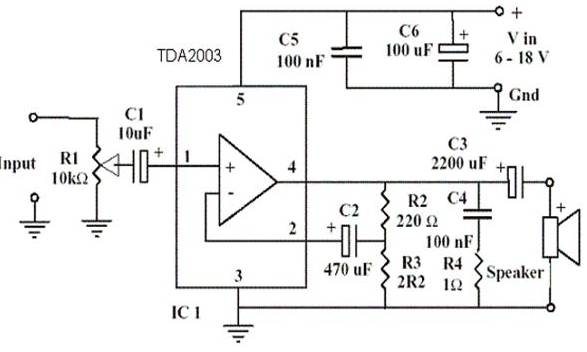
This is one of my favorites. The LM386 is a low voltage audio power amplifier. It can provide 125mW to 750mW, enough for any project that uses audio. This circuit can work with batteries, requires minimum external parts and...

This unit is designed to connect to an existing car stereo amplifier, providing the additional "punch" often desired in music playback by driving a subwoofer. Since very low frequencies are omnidirectional, a single amplifier is needed to power this...
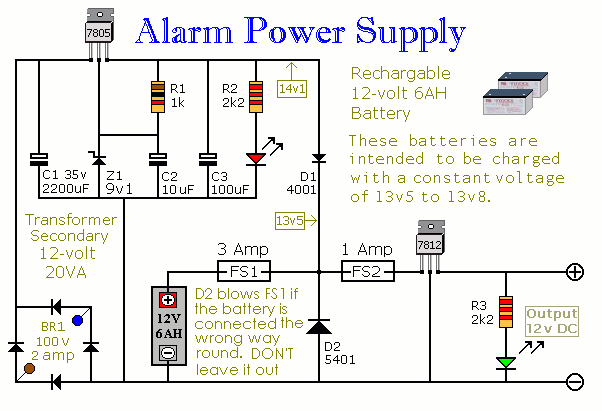
This Power Supply is suitable for the Modular Burglar Alarm. However, it has other applications. It is designed to provide an output of 12-volts, with a current of up to 1-amp. In the event of mains failure, the back-up...
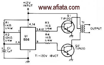
The first section of the 555 timer is configured as an astable oscillator, with R2 and C1 determining the frequency. The output is accessible at pin 5. The second section functions as a phase inverter, with its output available...
The simplest way to harness free available energy is by utilizing solar cells. A single efficient solar cell, when paired with a well-configured HHO generator, can produce a significant amount of gas suitable for various applications, all without incurring...
An amplifier device accepts a varying input signal and produces an output signal that varies in the same manner as the input but with a larger amplitude. The input signal can be a current, voltage, mechanical motion, or any...