
Thermocouple amplifier
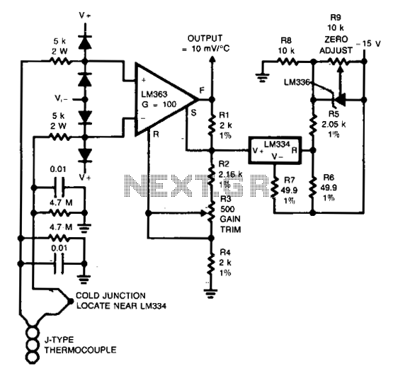
The input protection circuitry is designed to safeguard the amplifier from high voltage transients, specifically allowing a thermocouple to short to 120 Vac without incurring damage. This is crucial in applications where thermocouples are exposed to high voltage environments, ensuring the longevity and reliability of the amplifier.
For calibration, a 50 mV signal should be applied in place of the thermocouple. This serves as a reference input to adjust the output voltage accurately. The resistor R3 is then trimmed to achieve a specified output voltage (V0UT) of 12.25 V. This step is essential for ensuring that the amplifier responds correctly to the thermocouple's output during normal operation.
After the calibration of R3, the thermocouple should be reconnected to the circuit to resume normal function. Further fine-tuning is required by adjusting R9 to ensure the output is correct. This final adjustment allows for precise matching of the output signal to the expected values based on the thermocouple's characteristics, thereby ensuring accurate temperature measurements and system performance.
Overall, the combination of input protection and calibration steps ensures that the amplifier operates reliably in high-voltage environments while maintaining accurate readings from the thermocouple.Input protection circuitry allows thermocouple to short to 120 Vac without damaging the amplifier. Calibration: Apply a 50 mV signal in place of the thermocouple. Trim R3 for V0UT = 12.25 V. Reconnect the thermocouple. Trim R9 for correct output. 🔗 External reference
Related Circuits
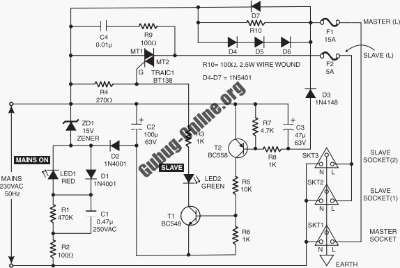
This circuit design features a modular arrangement that enables users to select only the modules best suited to their needs, allowing for the construction of a chain ranging from one to five modules in length. For those seeking a...
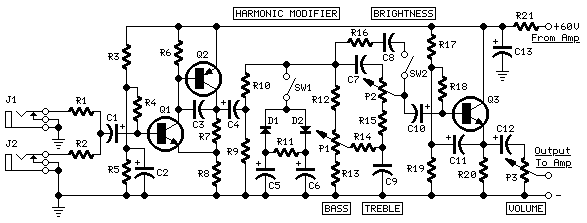
This design utilizes a well-established circuit topology for a power amplifier, employing a single-rail supply of approximately 60V and capacitor coupling for the speakers. The advantages for a guitar amplifier include simplified circuitry, even for relatively high power outputs,...
Although many album titles that were once available on vinyl are gradually being released on CDs, not all titles are accessible. It is possible that there are valuable records in a collection that one might wish to convert to...
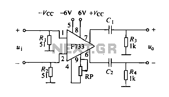
The F733 integrated wideband amplifier is a common-emitter configuration that features a total wideband amplifier with an internal feedback circuit. It is compact, offers zoom capability, and exhibits excellent circuit stability. The F733 circuit, as illustrated in the accompanying...
More: The provided input lacks specific details or context regarding an electronic circuit or schematic. To create a comprehensive electronic schematic description, it is essential to include key components, their interconnections, and the overall functionality of the...
This is a circuit that ensures that you can connect two amplifiers together so you get more power. When called in bridge linking two amplifiers plus you can link the outputs of the amplifiers to the speaker. One of...