
Thermostat for 1KW Space Heater (SCR controlled) circuit
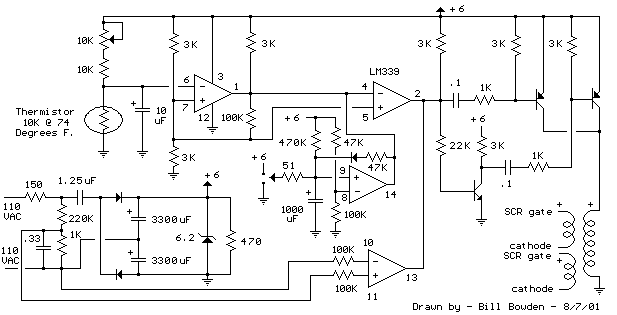
The described circuit utilizes a heating element that operates in conjunction with two SCRs arranged in a back-to-back configuration, allowing for controlled power delivery based on the alternating current (AC) supply. The SCRs serve as electronic switches that can handle high power loads, making them suitable for applications such as heating systems where precise control of the power is necessary.
The pulse transformer plays a critical role in the operation of this circuit. Its three identical windings are strategically utilized to ensure that the SCRs are triggered correctly. The first two windings are responsible for generating the trigger pulses that initiate the conduction of the SCRs. The third winding is connected to a PNP transistor pair, which functions to provide the necessary timing for the trigger pulses. This arrangement ensures that the SCRs are activated at the onset of each half-cycle of the AC waveform, allowing for efficient power control and minimizing the risk of overheating.
The alternating nature of AC voltage means that the polarity changes direction, which is why only one of the SCRs conducts at any given time. This is a critical feature of the design, as it prevents both SCRs from conducting simultaneously, which could lead to short-circuiting or damage to the components. By controlling which SCR is triggered based on the AC polarity, the circuit effectively manages the flow of current to the heating element, allowing for consistent and reliable operation.
In summary, this circuit design exemplifies an effective method for controlling a heating element using SCRs and a pulse transformer, ensuring efficient power management while maintaining safety and reliability in operation.The heater element (not shown) is connected in series with two back to back 16 amp SCRs (not shown) which are controlled with a small pulse transformer. The pulse transformer has 3 identical windings, two of which are used to supply trigger pulses to the SCRs, and the third winding is connected to a PNP transistor pair that alternately supply pulses to the transformer at the beginning of each AC half cycle.
The trigger pulses are applied to both SCRs near the beginning of each AC half cycle but only one conducts depending on the AC polarity.. 🔗 External reference
Related Circuits
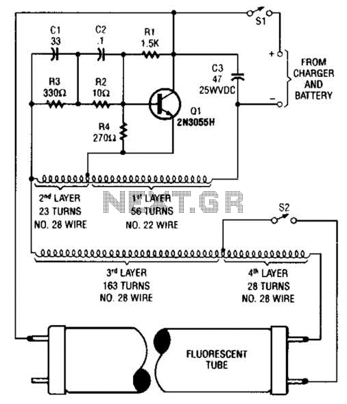
A 2N3055 oscillator (Q1) drives a homemade transformer, wound on a Vk ferrite rod. S2 is used as a filament switch and can be eliminated if desired. A 20-W fluorescent tube is recommended. The supply voltage is 12 V. The...
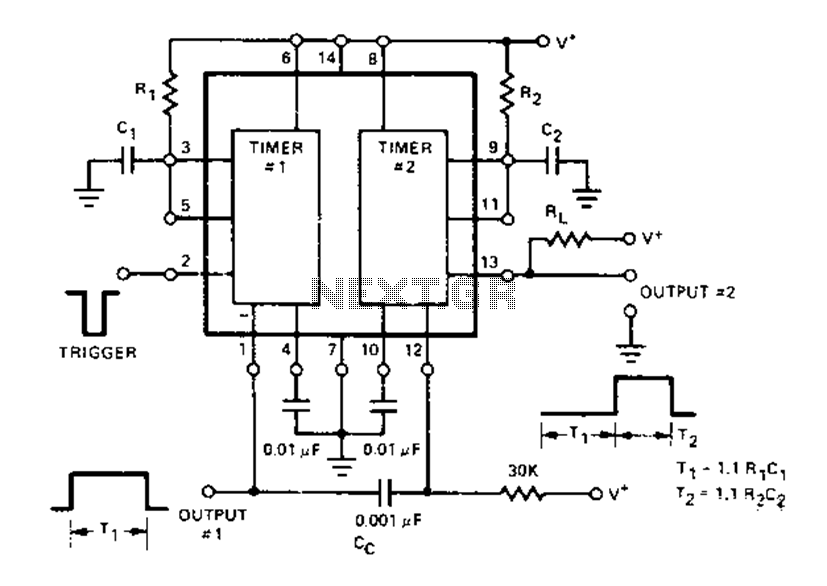
The Dual Timer Exar XR-2556 features a timing mechanism that can be triggered through capacitive coupling on a secondary timing pin. When a trigger input is engaged, the duration T1 can be set to 1.1R1C1, resulting in an increased...

A laser diode TOLD9200 (Toshiba) serves as a source of laser light. Q3, Q2, and SI constitute a touch switch to control the laser. L1 is an RF pickup coil designed to extract energy from an RF-type battery charger....
The 2.25-MHz oscillator Q1 drives amplifier Q2 and XTAL1, an ultrasonic transducer. The transducer is a lead zirconate-titanate type. Taps on T1 and T2 provide low-impedance drive points. The circuit consists of a 2.25-MHz oscillator (Q1) that serves as the...
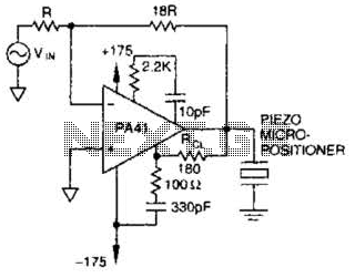
The PA41 from Apex Microtechnology is utilized to drive a piezoelectric micropositioner. The drive voltage is less than 20 V peak-to-peak at the input. The PA41 is a high-performance power amplifier designed specifically for driving piezoelectric devices, which require precise...
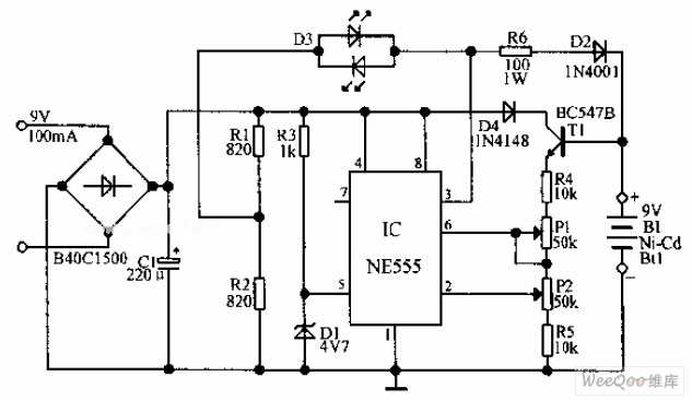
An automatic Ni-Cd battery charger circuit is depicted in the provided image. The internal comparator of the NE555 timer is configured to a reference voltage of 4.7V using a Zener diode. When the voltage at pin 6 exceeds this...
Warning: include(partials/cookie-banner.php): Failed to open stream: Permission denied in /var/www/html/nextgr/view-circuit.php on line 713
Warning: include(): Failed opening 'partials/cookie-banner.php' for inclusion (include_path='.:/usr/share/php') in /var/www/html/nextgr/view-circuit.php on line 713