
Three-State Continuity Tester
The continuity tester circuit is designed to accurately assess the resistance of connections by providing a clear visual indication through the use of LEDs. The operational amplifier IC1c plays a crucial role in amplifying the voltage across R2, which is critical for determining the resistance levels. The window comparator configuration, utilizing IC1a and IC1b, enables precise comparison of the amplified voltage against predefined thresholds set by resistors R4 and R6. This ensures that the circuit can categorize the resistance into three distinct ranges: high, medium, and low.
The use of potentiometer P1 allows for user calibration of the resistance thresholds, providing flexibility in the circuit's operation. This adjustability is essential for applications requiring varying sensitivity levels. The design also incorporates a trade-off between the potential difference across R2 and the test current, which must be managed to maintain circuit integrity and performance.
The power supply requirements of the LM324 ensure compatibility with a range of applications, and the inclusion of R1 is a necessary safety feature to protect the operational amplifier from excessive input voltages. The driving capability of the 4049 inverters ensures that the LEDs can operate effectively, providing a reliable visual output that is critical in diagnostic and testing scenarios. Overall, this continuity tester circuit combines functionality, adaptability, and safety, making it a valuable tool in electronic testing and maintenance.The continuity tester can distinguish between high-, medium-, and low-resistance connections. When there is a conductance between the inputs, which are linked to small probes, a current flows from the +9 V line to earth via R1 and R2. The consequent potential difference, p. d. , across R2 is used to determine the transfer resistance. Operational amp lifier IC1c amplifies the p. d. across R2 to a degree that is set with P1. A window comparator, IC1a and IC1b, likens the output of IC1c to the two levels set with potential divider R4 R6. Depending on the state of the outputs of the two comparators, three light-emitting diodes (LEDs) are driven via the gates and inverters contained in IC3 and IC2 respectively in such a way that they indicate the transfer resistance in three categories.
When the resistance is high, green diode D3 lights; when it is of medium value, yellow diode D2 lights, and when it is low, red diode D1 lights. The levels at which the diodes light is set with P1, but note that in any case the minimum value depends on the p.
d. across R2. It is possible to reduce the value of the p. d. to enable lower transfer resistances to be detected, but this would mean an increase in the test current through R2. With values as specified, the circuit in its quiescent state draws a current of about 17 mA, but in operation each LED adds about 10 mA to this.
The LM324 (IC1) may be operated from a single supply line: R1 prevents the voltage at the input from reaching the level of the supply line (which is not permissible). The supply voltage may be 5 18 V. The LEDs are driven directly by the inverters in the 4049 (IC2), which can switch currents of up to 20mA to earth.
🔗 External reference
Related Circuits
A good/bad transistor tester is an instrument designed to determine the operational status of a transistor, indicating whether it is functional or defective. This device provides a simple binary assessment, confirming if the transistor has a gain equal to...
This circuit allows for the testing of quartz resonators within a frequency range of 32 kHz to 24 MHz. The operational status of the quartz resonator is indicated by a diode signaling an LED and an acoustic signal. The circuit...
Yes, it does charge the inductor again. Diodes are beneficial as they do not charge the inductor back but dissipate a significant amount of instantaneous power due to the forward voltage drop. One approach would be to monitor the...
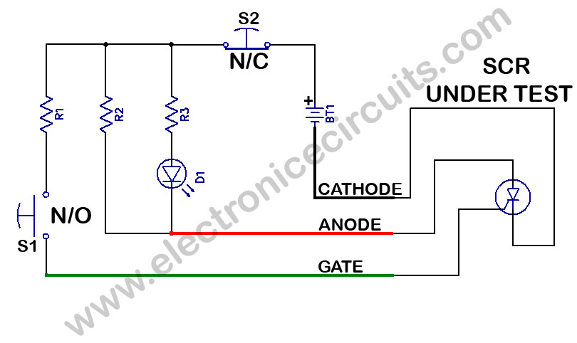
SCR Tester Circuit. The device under test, cathode, anode, and gate are connected to the unit's cathode, anode, and gate terminals. The SCR tester circuit is designed to evaluate the functionality of Silicon Controlled Rectifiers (SCRs) by facilitating connections to...
The design shown will test PNP and NPN transistors, diodes and SCRs both "in-situ" (equipment of course de-energised) and also by direct connection to a stand-alone component. It is a simple GO/NOGO test which can identify diode and transistor...
This small transistor tester employs a simple visual indication system to perform a quick go/no-go check on both NPN and PNP transistors. When testing a functioning NPN transistor, the green LED (D1) will flash, while the red LED will...
Warning: include(partials/cookie-banner.php): Failed to open stream: Permission denied in /var/www/html/nextgr/view-circuit.php on line 713
Warning: include(): Failed opening 'partials/cookie-banner.php' for inclusion (include_path='.:/usr/share/php') in /var/www/html/nextgr/view-circuit.php on line 713