
Three-year-led-flasher
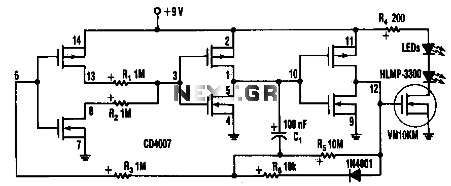
Inserting two 1-MΩ resistors, R1 and R2, in the output stage of one of the circuit's inverters limits the current needed by the oscillator tone to more than a few pA. This circuit includes a CD4007 package, which contains three CMOS inverters and forms a standard three-inverter oscillator. Resistors R1 and R2, in series with separate drains on inverter pins 8 and 13, limit the oscillator's supply current. Capacitor C1 and resistor R5 set the off time of the oscillator, while R6 sets the on time. A VN10KM small-power FET, current-limited by R4, drives two HLMP-3300 LEDs. The LEDs consume approximately 20 mA for 1 ms, and their average current determines battery life. Since the LEDs in the circuit flash at 1 Hz, the average current drain is about 1/1000 of 20 mA, or 20 pA. A 9-V battery should last approximately three years at the current drain, essentially the shelf life of an alkaline battery.
The circuit design incorporates a CD4007 integrated circuit, which is an essential component for constructing CMOS inverters. The configuration of the three inverters allows for the creation of a reliable oscillator that operates at low power. The use of two 1-MΩ resistors, R1 and R2, in the output stage is critical for controlling the current flow through the oscillator, ensuring that it operates efficiently without exceeding the specified limits.
The oscillator's timing characteristics are determined by the combination of capacitor C1 and resistor R5, which control the duration of the off time, while resistor R6 is responsible for defining the on time. This combination enables the oscillator to produce a stable frequency output suitable for driving the LEDs.
The VN10KM FET serves as a switch that activates the two HLMP-3300 LEDs. The current through the LEDs is limited by resistor R4, which is necessary to prevent damage to the LEDs due to excessive current. The LEDs are designed to flash at a frequency of 1 Hz, resulting in a very low average current consumption of approximately 20 pA, which is critical for extending the battery life. The choice of a 9-V battery is appropriate for this circuit, as it provides sufficient voltage to operate the components while ensuring a long operational lifespan, estimated at around three years, which aligns with the typical shelf life of alkaline batteries.
This circuit exemplifies efficient power management in low-energy applications, making it suitable for battery-operated devices where longevity is a key requirement. The careful selection of components and their configuration illustrates best practices in low-power circuit design.Inserting two 1-MO resistors, R1 and R2, in the output stage of one of the circuit"s inverters limits the current needed by the oscillator tone more than a few pA. This circuit includes a CD4007 package, which has three CMOS inverters. It forms a standard three-inverter oscillator. Resistors R1 and R2, in series with separate drains on inverter pins 8 and 13, limit the oscillator"s supply current.
Capacitor C1 and resistors R5 set the off time of the oscillator, C1; R6 sets the on time. A VN10KM small-power FET, currentlimited by R4, drives two HLMP-3300 LEDs. The LEDs consume about 20 mA for 1 ms. Their average current determines battery life. Since the LEDs in the circuit flash at 1 Hz, the average current drain is about 1/1000 of 20 mA, or 20 p.A. A 9-V battery should last about three years at the current drain-essentially the shelf life of an alkaline battery.
🔗 External reference
Warning: include(partials/cookie-banner.php): Failed to open stream: Permission denied in /var/www/html/nextgr/view-circuit.php on line 713
Warning: include(): Failed opening 'partials/cookie-banner.php' for inclusion (include_path='.:/usr/share/php') in /var/www/html/nextgr/view-circuit.php on line 713