
Through a small pulse transformer output of one transistor trigger circuit
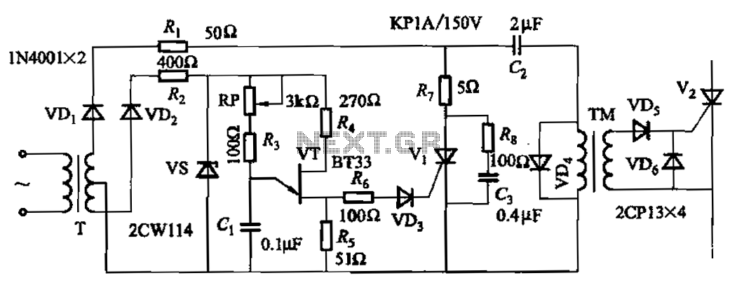
The circuit incorporating the adjustment potentiometer RP is designed to facilitate precise control over the phase shift of a pulse signal. This phase shift circuit operates within a specified range of 0 to -1600 degrees, which indicates the potential for significant timing adjustments in signal processing applications. The use of an adjustment potentiometer enhances the sensitivity of the phase shift, allowing for fine-tuning to achieve desired operational characteristics.
In practical applications, this circuit can be utilized in various electronic systems that require precise timing adjustments, such as in communication systems, audio processing, or modulation schemes. The potentiometer RP serves as a variable resistor, enabling the user to alter the resistance in the circuit, thereby changing the voltage levels and consequently affecting the phase of the output pulse.
The design may include additional components such as capacitors and operational amplifiers to stabilize the circuit and ensure the output remains within the desired parameters. Properly selecting the values for these components is critical to achieving the intended phase shift and maintaining signal integrity. Overall, the phase shift circuit with the adjustment potentiometer RP is a valuable tool in electronic design, providing versatility and control over signal timing.Adjustment potentiometer RP, can change the pulse phase shift range. The phase shift circuit is in the range of 0. -1600 Higher sensitivity.
Related Circuits
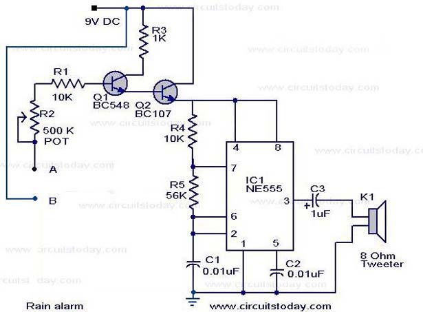
The operation of the rain alarm circuit is explained in detail. The rain alarm project is outlined along with a circuit diagram. The rain alarm circuit is designed to detect the presence of rain and alert users through an audible...
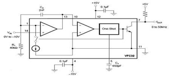
The circuit diagram of a voltage-to-frequency (V/F) converter is presented, designed to handle negative input voltage. It employs the VFC32 voltage-to-frequency converter, which is commonly utilized in various applications. The V/F converter circuit is essential in converting an analog voltage...
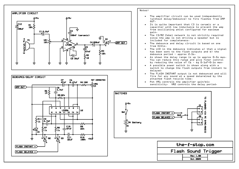
The following is a clear description of the final version of the trigger used and a circuit diagram for anyone wishing to construct their own. The initial version of this trigger was a simple single transistor amplifier, a piezo...
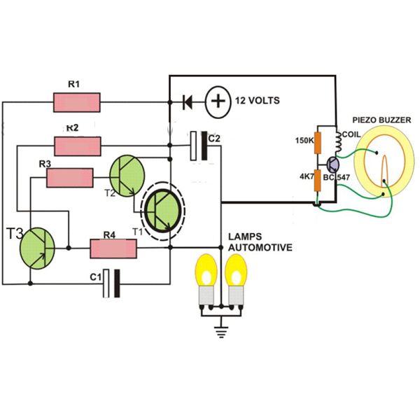
This circuit is designed to create a flasher unit for a motorbike. It is a simple turn signal flasher circuit that can be easily built and installed in any two-wheeler for the desired functionality. The circuit uses only two...

A circuit designed for a phone photo camera flash that delivers a peak current of 200mA. It utilizes the AAT3110-4.5 capacitive charge pump chip to boost and regulate the lithium battery voltage to 4.5V. This voltage powers a series...
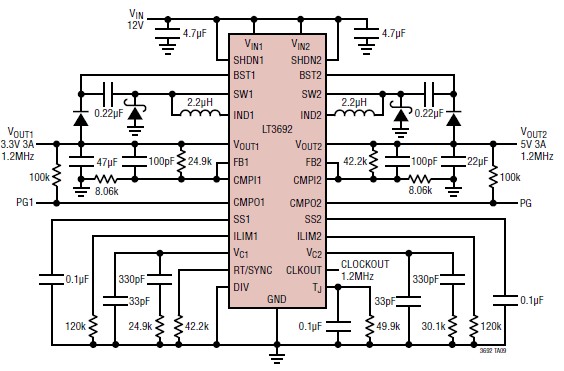
The LT3692 dual current mode PWM step-down DC-DC converter circuit, featuring two internal 3.5A switches, can be designed into a simple power supply circuit suitable for various electronic applications, such as distributed supply regulation or automotive circuits. The LT3692...