
Thyristor Tester

The thyristor testing circuit is designed with versatility and user-friendliness in mind. The inclusion of switch S3 allows for comprehensive testing of triacs across all quadrants, which is essential for applications where bidirectional control is required. The configuration of the circuit with S1 for standard thyristors ensures that the user can easily switch between different types of thyristors without complex adjustments.
Resistors R1 and R2 are critical components that set the testing current, and their values must be carefully calculated to ensure that 28 mA is achieved without exceeding the power ratings of the resistors. The choice of a holding current of 125 mA via R3 provides a reliable operational threshold for maintaining conduction in the thyristor post-triggering, which is vital for applications that require stable operation after initial activation.
The use of two LEDs (D1 and D2) not only provides visual feedback but also enhances the circuit's usability by allowing quick identification of the conducting state. This feature is particularly useful in educational settings or during troubleshooting processes, where rapid assessment is necessary.
The circuit's reset functionality via S4 ensures that tests can be conducted repeatedly without manual disconnection and reconnection of the components, enhancing efficiency. The crocodile clips on connector K1 offer a practical solution for connecting various thyristors, simplifying the testing process while minimizing the risk of incorrect connections.
In cases where specific testing conditions are required, the ability to modify the trigger current by adjusting R1 and R3 or using a variable power supply adds a layer of adaptability to the circuit. This flexibility is especially beneficial for advanced users who may need to test thyristors under varying conditions to evaluate performance or troubleshoot issues effectively. Careful attention must be paid to resistor ratings to prevent overheating, particularly when using higher currents or variable supplies. Overall, this thyristor testing circuit is a well-thought-out design that caters to both basic and advanced testing needs in electronic applications.The circuit in the diagram is a very handy tool for rapidly checking all kinds of thyristor (SCR, triac, ). In case of a triac, all four quadrants are tested, which is done with S3, while in case of a standard thyristor, a positive power supply and trigger current need to be set, which is done with S1.
The value of resistors R1 and R2 is chosen to obtain a current of about 28 mA, which is more than sufficient for most thyristors. The hold current is determined by R3, and is 125 mA, which is more than adequate to keep the thyristor in conduction after it has been triggered. Since D1 is a red, low-current LED, and D2 a green, low-current LED, it can be seen in a wink in which quadrant the thyristor conducts.
Testing is started with S2, and the circuit is reset with S4 after the test has been concluded. Three short lengths of circuit wire terminated into insulated crocodile clips on connector K1 will be found very convenient for linking any kind of thyristor to the circuit. Mind correct connections, though: in the case of a triac, MT1/A1 is linked to earth, the gate to S2 and MT2/A2 to R3; in the case of a standard thyristor, the anode is linked to R3, the cathode to earth, and the gate to S2.
If, in a rare case the trigger current needs to be altered, this can be done by changing the value of resistors R1 R3 as appropriate. The trigger current may also be made variable by the use of a variable power supply. If that is done, make sure that the dissipation in the resistors is not exceeded. 🔗 External reference
Related Circuits

The circuit does not guarantee the testing of all defective MOSFETs or all fault conditions in MOSFETs. If the MOSFET is functional, it will operate within the astable multivibrator circuit, resulting in the LED flashing. The described circuit employs an...
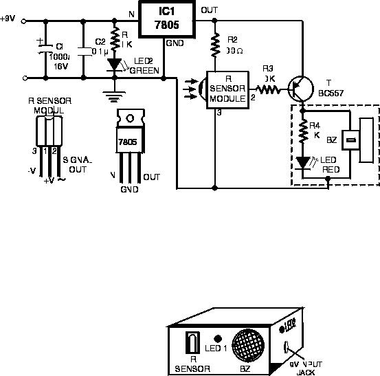
Here is a handy gadget for testing of infrared (IR) based remote control transmitters used for TVs and VCRs etc. The IR signals from a remote control transmitter are sensed by the IR sensor module in the tester and...

This small circuit is designed to verify the basic functionality of an infrared remote control unit. The circuit utilizes a straightforward approach by connecting a piezo buzzer directly to an IR receiver integrated circuit (IC). This configuration is as...
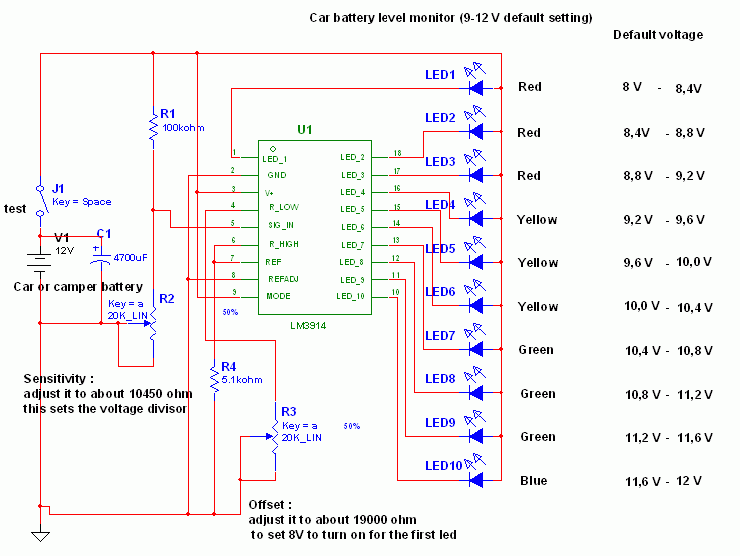
This circuit utilizes the widely available and user-friendly LM3914 integrated circuit (IC). The LM3914 is straightforward to operate, does not require external voltage regulators due to its built-in voltage regulation, and can be powered by nearly any voltage source....
Firstly, we will describe the add-on version for the 5x7 Display as this is the cheapest version and, quite frankly, it only deserves a few dollars as a piece of test equipment. It's all the rage to have an...
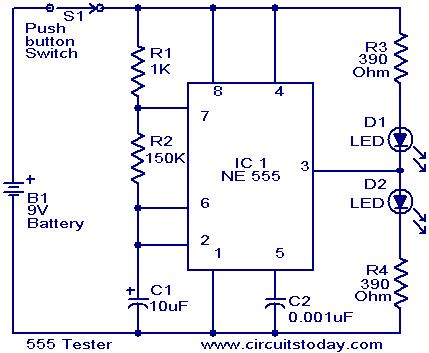
The NE555 timer is configured as an astable multivibrator. When the push button switch S1 is pressed, the LEDs D1 and D2 will flash alternately. When the output is high, D2 will illuminate, and when the output is low,...