
Time Switch
The circuit utilizes a high-decibel audio output mechanism to ensure that the alarm is audible even in noisy environments. It incorporates a sound-generating component, such as a piezoelectric buzzer or a small speaker, which is capable of producing a range of frequencies to create a more attention-grabbing sound.
The design may include a microcontroller or timer IC that allows users to set the desired wake-up time accurately. This component can be programmed to activate the alarm at the set time, triggering the audio output device. Additionally, the circuit may feature adjustable volume controls to cater to individual preferences, ensuring that the alarm can be customized for different settings.
Power supply options for this circuit can vary, including battery-powered designs for portability or AC mains-powered versions for stationary use. A power management system may be integrated to optimize battery life and prevent over-discharge in battery-operated models.
Furthermore, the circuit may include visual indicators, such as LEDs, to provide a visual cue when the alarm is set or activated. This can enhance usability, especially in low-light conditions.
In summary, this wake-up alarm circuit is engineered to deliver a loud and effective alert, making it ideal for users who require a reliable waking mechanism. Its features prioritize user customization and adaptability, ensuring it meets the diverse needs of early risers.This circuit is especially designed for those who often need to wake up early in the morning. Ordinary alarms in electronic watches are not loud enough an.. 🔗 External reference
Related Circuits
The extensive network of telegraph wires that once enveloped the nation has disappeared, much like a spider's web is swept away by a broom. Please note that the information below is outdated. Dial-up Morse is no longer commonly used....
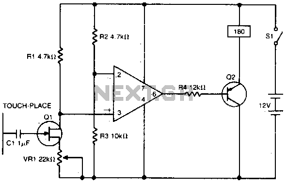
A high impedance input is provided by Q1, a general-purpose field effect transistor. The 741 operational amplifier is utilized as a sensitive voltage level switch, which subsequently activates Q2, a medium current PNP bipolar transistor. This action energizes a...
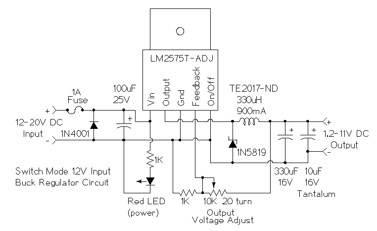
This is a simple buck mode switching regulator circuit diagram. This circuit is more efficient; switch mode regulators convert DC input voltage to pulses of high DC voltage. The DC pulses are used to charge a storage capacitor to...
This circuit generates a constant current, constant voltage switched-mode power supply (SMPS). It is designed to efficiently charge a battery using a constant current, constant voltage approach. The circuit operates as a constant current, constant voltage SMPS, which is crucial...
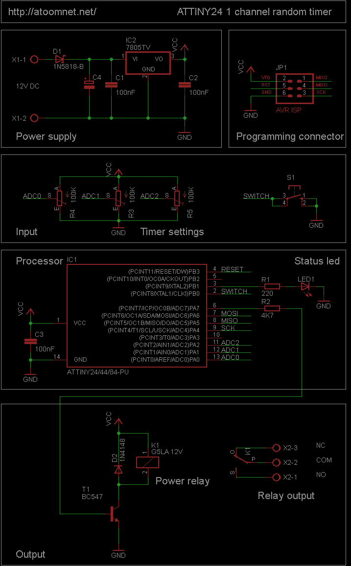
This random timer circuit is based on an Atmel ATTINY24 AVR driving one power relay. It can be used to switch on and off other circuits randomly. For instance, in a model railroad setup, this circuit can activate and...
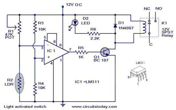
A simple light-activated switch circuit with a diagram and schematic using IC LM311 wired as a voltage comparator and an LDR that acts as a light sensor. The described circuit utilizes the LM311 integrated circuit, which functions as a voltage...
Warning: include(partials/cookie-banner.php): Failed to open stream: Permission denied in /var/www/html/nextgr/view-circuit.php on line 713
Warning: include(): Failed opening 'partials/cookie-banner.php' for inclusion (include_path='.:/usr/share/php') in /var/www/html/nextgr/view-circuit.php on line 713