
Timer 1 Minute To 400 Hrs Circuit
The circuit design begins with the 555 timer, configured in astable mode to generate a continuous square wave output. The frequency of this output can be adjusted by varying the resistance and capacitance in the timing network. The output frequency from the 555 timer serves as the input for the two 4017 decade counters. Each 4017 counter divides the frequency by ten, allowing for a broad range of output frequencies depending on the configuration of the circuit.
The 4020 binary counter is employed to further divide the frequency, providing additional versatility in the timing range. By using the SP3T range switch, the user can select which counters are active in the circuit, effectively enabling the selection of different frequency ranges. This feature allows for customized timing applications, making the circuit suitable for various electronic timing tasks.
The output from the last counter can be used to drive other components or circuits, such as LEDs for visual indication or additional logic circuits for further processing. Careful consideration should be given to the power supply requirements and the load connected to the output to ensure reliable operation across the entire frequency range. Overall, this ultra wide range timer circuit provides a flexible and efficient solution for timing applications in various electronic projects. This ultra wide range timer uses a 555 timer base, two 4017Bs and a 4020B that act as frequency dividers that can be switched in and out. SI is a SP3T range switch. 🔗 External reference
Related Circuits
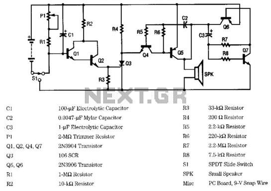
The circuit employs an infrared (IR) phototransistor, designated as Q1, to sense the IR output signal from a remote control. The output from Q1 is then amplified by a PNP transistor, labeled Q2, which activates LED1. This illumination indicates...
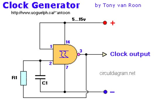
The following diagram is the clock generator circuit diagram built using NAND gate logic integrated circuits (ICs). The circuit can utilize either the IC 7400, which is a TTL type, or the IC 4011, which is a CMOS type....
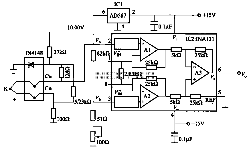
The AD587 is a precision voltage reference providing a 10 V output, generated using a 27 kΩ resistor along with a compensation diode (1N4148) and a thermocouple. This setup connects to the VI + N terminal of a differential...

The circuit connection is illustrated in figures a and b. In figure a, a star-shaped winding is used with shunt capacitance, while figure b depicts a triangular winding with capacitance connected in parallel. The working capacitance (Cc) is calculated...
DTMF-based Robo Car design using the 8051 microcontroller project. This project demonstrates a method to control a domestic system using the DTMF tone generated by a telephone instrument when the user presses the keypad buttons of a mobile phone...

This design circuit outlines a simple, low-cost, and ultra-compact VHF/UHF Low-Noise Amplifier (LNA) that can be implemented using the MAX2664 and MAX2665 devices, which are specifically tailored for VHF/UHF applications. The MAX2664 operates within the UHF frequency range of...
Warning: include(partials/cookie-banner.php): Failed to open stream: Permission denied in /var/www/html/nextgr/view-circuit.php on line 713
Warning: include(): Failed opening 'partials/cookie-banner.php' for inclusion (include_path='.:/usr/share/php') in /var/www/html/nextgr/view-circuit.php on line 713