
TMP01 Fahrenheit Scale Temperature Sensor
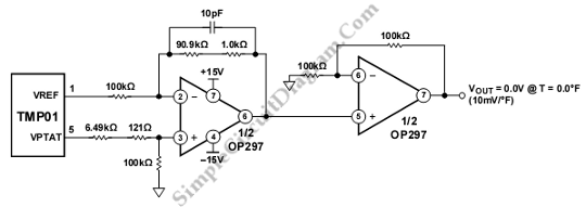
The TMP01 is a precision temperature sensor that provides an analog voltage output proportional to temperature. The circuit typically operates in the range of -40°C to +125°C, translating to a voltage output of 0V to 5V, where the output voltage increases with temperature. The sensor utilizes a bandgap reference to achieve high accuracy and stability over varying environmental conditions.
In this schematic, the TMP01 is connected to a power supply, usually +5V, which powers the sensor. The output voltage (VOUT) from the TMP01 is proportional to the temperature in Fahrenheit, calculated using the formula: VOUT = (Temperature in °F × 10mV) + 500mV. Hence, at 0°F, the output voltage will be 0.5V, and at 125°F, it will reach approximately 2.5V.
To interface the TMP01 with a microcontroller or other reading devices, the output can be connected to an analog-to-digital converter (ADC). This allows digital processing of the temperature reading. Additionally, a filtering capacitor may be added to the output to smooth the signal and reduce noise, ensuring a more stable reading.
The circuit may also include resistors for biasing and protection, as well as a calibration mechanism to ensure accurate temperature readings. Overall, this schematic provides a straightforward and effective means of measuring temperature in Fahrenheit using the TMP01 sensor.This schematic diagram is about TMP01 Fahrenheit Scale Temperature Sensor circuit. This circuit is used to convert VPTAT into an output that can be read.. 🔗 External reference
Related Circuits
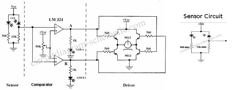
The following circuit illustrates the sensor circuit of an analog line follower robot. Features include control by a microcontroller and a sensor circuit. The sensor circuit for an analog line follower robot is designed to detect the presence of a...

The ADSP-2103 and ADSP-2105 are digital signal processors that interface with the AD7714. When the output is active, the ADSP-2103/2105 configuration includes the RFS non-TES non-terminal set to a low level, while the SCLK terminal is configured for serial...
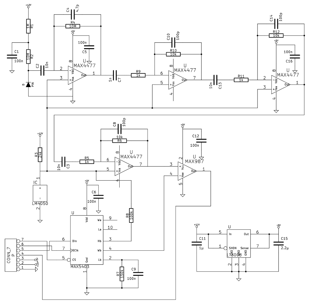
A noteworthy application note from Maxim detailed a gamma-photon detector utilizing a standard PIN diode as its sensing element. The circuit design appeared straightforward, prompting the decision to construct it, as having multiple measurement instruments is always beneficial. The gamma-photon...
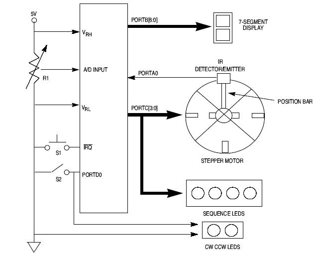
This article explains how to design a stepper motor system using an 8-bit Freescale microcontroller - MC68HC11E9. The design of a stepper motor system utilizing the 8-bit Freescale microcontroller MC68HC11E9 involves several key components and considerations to ensure effective control...
This circuit is a motion detection sensor that utilizes a light source and detector as an infrared motion detector. It incorporates components such as a light-emitting diode (LED), a phototransistor, a transmitter, a receiver, an NE555 timer configured as...

A thermistor (R1) is compared with a reference resistor (R2) in a Wheatstone bridge circuit. The output of comparator U1 goes high, which triggers U2. U2 introduces a delay of approximately 25 seconds. After 15 seconds, LED1 illuminates, U3...
Warning: include(partials/cookie-banner.php): Failed to open stream: Permission denied in /var/www/html/nextgr/view-circuit.php on line 713
Warning: include(): Failed opening 'partials/cookie-banner.php' for inclusion (include_path='.:/usr/share/php') in /var/www/html/nextgr/view-circuit.php on line 713