
Toggle Switch with relay
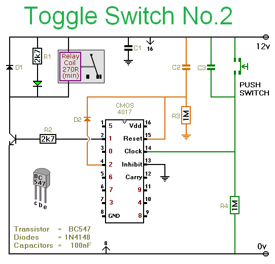
The described circuit utilizes a momentary push-to-make switch to control the operation of a relay. Upon the first press of the button, the relay coil is energized, allowing current to flow through the relay contacts, which can then control a connected load. A second press of the button interrupts the current to the relay coil, de-energizing it and opening the contacts, thus turning off the load.
The schematic includes a single-pole relay, but it is noted that a multi-pole relay can be used if the application requires multiple outputs to be controlled simultaneously. The relay's coil voltage is flexible, accommodating a range from 5 to 15 volts, which provides versatility in power supply selection. It is essential to choose a relay that matches the voltage of the power supply to ensure proper operation.
The push-to-make switch should be rated appropriately for the current and voltage levels expected in the circuit. When selecting the relay, parameters such as coil resistance, contact rating, and switching speed should also be considered based on the requirements of the load being controlled. The circuit can be implemented on a breadboard for prototyping or designed on a printed circuit board (PCB) for permanent installations.Pushing the button once will energize the relay. Pushing the same button a second time will de-energize the relay. Any simple momentary action push-to-make switch will do. I've drawn the circuit with a single pole relay. But you can use a multi-pole relay if it suits your application. The circuit will work at anything from 5 to 15-volts. All you need do is select a relay with a coil voltage that suits your supply. The LE 🔗 External reference
Related Circuits
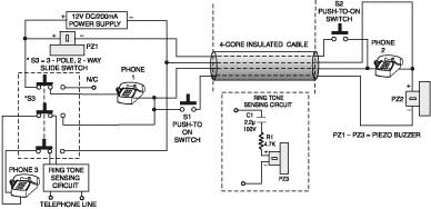
A two-line intercom with a telephone changeover switch. This circuit can connect two telephones in parallel and function as a 2-line intercom. Typically, a single telephone is connected to a. The two-line intercom circuit is designed to facilitate communication between...
Many microcontroller designs typically integrate various interfacing methods. A microcontroller (µC) system can be viewed as a system that reads from inputs. Microcontroller systems are versatile platforms that facilitate the integration of multiple interfacing methods to interact with various peripherals...
The game was originally designed to position three balls locked in holes on a slowly rotating ring around the Deadworld. Once the third ball was secured, a mechanical arm would release them, dropping the balls onto the playfield. This...
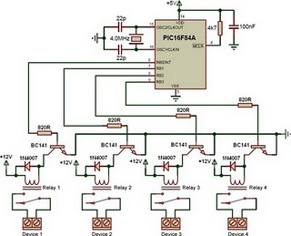
This is a relay driver based on a PIC16F84A microcontroller. The board includes four relays, allowing control of four distinct outputs. The relay driver circuit utilizing the PIC16F84A microcontroller is designed for controlling multiple devices or systems through relay activation....
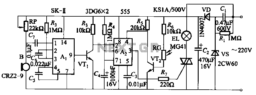
This circuit utilizes a dedicated voice integrated circuit (AI) of the SK type, which incorporates an internal bistable multivibrator and three inverting amplifiers. The 555 integrated circuit (IC) A2 is employed for delay control. The described circuit is designed to...
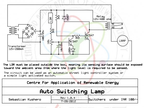
The circuit is designed to switch off a specific lamp or a group of lamps based on varying ambient light levels. Once constructed, it will turn off a lamp at dawn and turn it on at dusk. The power...
Warning: include(partials/cookie-banner.php): Failed to open stream: Permission denied in /var/www/html/nextgr/view-circuit.php on line 713
Warning: include(): Failed opening 'partials/cookie-banner.php' for inclusion (include_path='.:/usr/share/php') in /var/www/html/nextgr/view-circuit.php on line 713