
Tone Controls
The circuit described is a versatile audio control system designed to manipulate treble and bass frequencies while managing overall volume. The power supply requirement of 12V suggests compatibility with common audio equipment. The adjustable resistor R1 allows for customization of the circuit to accommodate higher voltage sources, enhancing the circuit's adaptability.
VR1 and VR2, as treble and volume controls respectively, utilize linear potentiometers, which provide a smooth transition in audio levels. The inclusion of C1 as an input isolating capacitor serves to prevent DC offset from affecting subsequent stages, promoting clearer audio reproduction. The choice of a 47nF capacitor for C1 is standard for audio applications, ensuring adequate bandwidth while preventing low-frequency noise from entering the circuit.
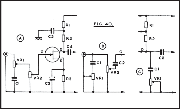
The configuration of the FET's source and drain circuits, as referenced in Figure 40, is critical for optimal performance. The FET's characteristics, including its transconductance and threshold voltage, will influence the overall gain and frequency response of the circuit. The use of a 2.2 megohm resistor at the gate ensures that the FET operates within its linear region, providing a stable DC operating point while allowing for AC signal processing.
The design allows for flexibility in component selection, which is essential in audio applications where personal preference plays a significant role. The ability to fine-tune the treble and bass response through VR1 and VR2 ensures that users can achieve their desired sound profile. Additionally, the potential for integrating this tone control into existing circuits without major modifications enhances its utility in various audio setups.
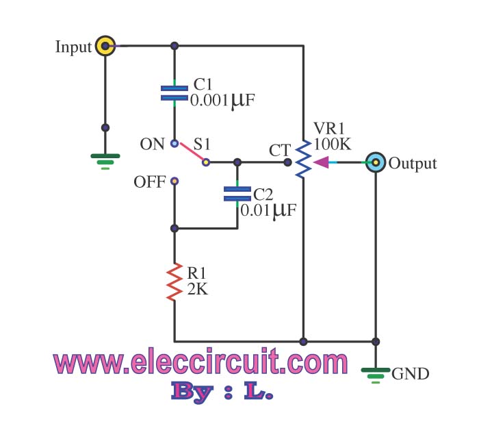
Overall, this circuit exemplifies a well-thought-out approach to audio signal processing, balancing flexibility, usability, and performance, making it suitable for both amateur and professional audio applications.Operation is from a 12v or similar supply, and R1 can be changed if necessary for higher voltages. In this and similar circuits there is considerable latitude in the choice of values for positions such as C1. At B VR1 is a top cut control, and VR2 the volume control. C2 is connected to the gate at G, and a 2. 2 megohm resistor provides the DC path from gate to negative line, other components being R1, R2, P3, C2, C3 and C4 as at A. Yet another top cut control is shown at C. Here, R1 and R2 are the some as R1 and R2 in A, C2 of A being included as at A. In some cases such a tone control can be added to an existing stage without any disturbance to the circuit board. C1 at C can be 47nF, and VR1 25k. Higher values may be fitted for VR1, but tend to make most of the audible effect of this control occupy only a small part of its rotation.
C1 can be increased, to give increased top cut. The results obtained with various component values are influenced by the impedance of the circuit. C1 is the input isolating capacitor, and may be unnecessary with some types of input. VR1 is for treble control. Treble is lifted with the wiper towards C2, whose reactance falls as frequency rises. With VR1 wiper towards C3, treble is reduced. VR2 similarly provides lift or cut in bass. Both are linear controls, supplying the volume control VR3 by means of R1. The source and drain circuits for the FET can be as in Figure 40. Again, values are to some extent a matter of choice, but there is little point in using components which will provide extreme degrees of cut or boost, which wilt never be required. It is also of advantage to have approximately flat reproduction with VR1 and VR2 central. 🔗 External reference
Related Circuits
Based on the classic Baxendall tone control circuit, this provides a maximum cut and boost of around 10dB at 10K and 50Hz. The first BC109C transistor (left hand side) is acting as a buffer. It provides the circuit with...
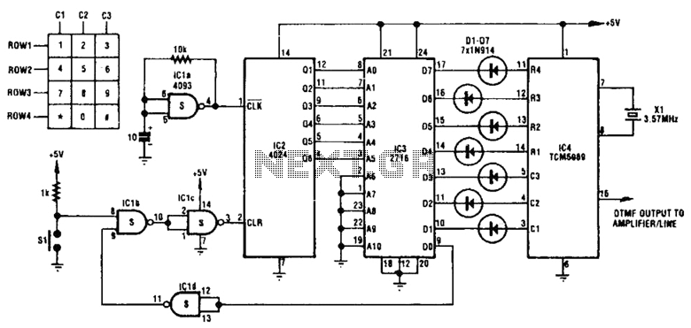
This project has an impractical requirement or utilizes components that are no longer available. It is provided for reference or inspiration only and is considered unsupported. The project displays telephone numbers decoded from tones, specifically telephone touchtones or Dual...
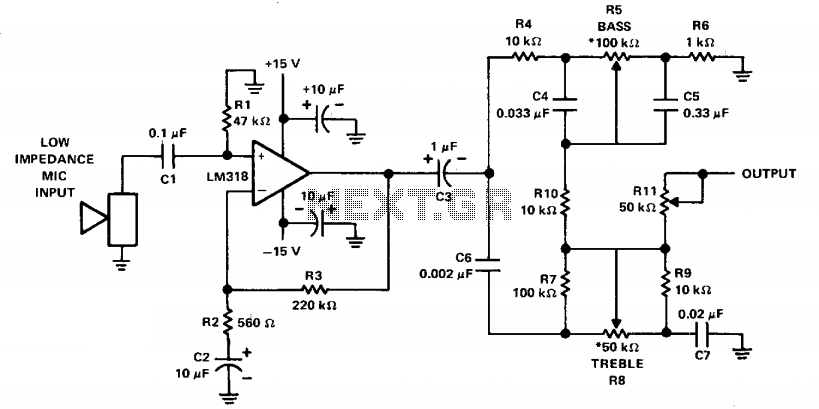
The LM318 operational amplifier is configured as a standard non-inverting amplifier. Resistor R1 (47 kΩ) provides a ground path for the bias current of the non-inverting input. The combination of R2 (560Ω) and C2 (10µF) creates a frequency roll-off...
The passive tone control circuit is designed to adjust the bass without expansion, utilizing resistors (R) and capacitors (C). It functions as a frequency filter and is easy to construct, requiring no external power supply. This circuit can be...
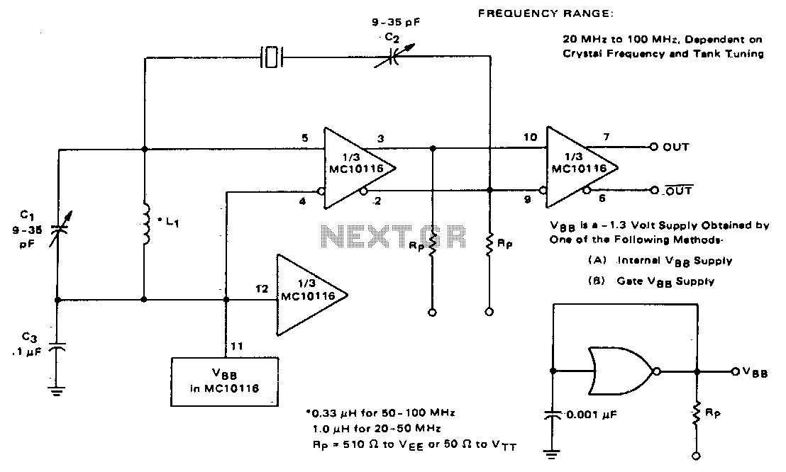
This circuit utilizes an adjustable resonant tank circuit that ensures operation at the desired crystal overtone. Capacitor C1 and inductor L1 form the resonant tank circuit, which can be adjusted to achieve a resonant frequency ranging from approximately 50...
This circuit utilizes inexpensive, commonly available components to generate a precise dial tone for telephone applications. The Intel 82C54 timer-counter (U1) produces square wave signals at frequencies of 350 Hz and 440 Hz, which are subsequently filtered by resistors...
Warning: include(partials/cookie-banner.php): Failed to open stream: Permission denied in /var/www/html/nextgr/view-circuit.php on line 713
Warning: include(): Failed opening 'partials/cookie-banner.php' for inclusion (include_path='.:/usr/share/php') in /var/www/html/nextgr/view-circuit.php on line 713