
Tone detector

The detector circuit is designed to selectively filter and process signals of a specific frequency while rejecting unwanted noise. The two-amplifier multiple feedback bandpass filter is critical in achieving a high Q factor, which enhances the circuit's selectivity and sensitivity to the desired frequency of 500 Hz. This filter configuration typically employs operational amplifiers configured in a feedback loop, allowing for precise tuning of both the center frequency and bandwidth.
The rectification stage, implemented using diode D1, converts the AC signal output from the bandpass filter into a DC voltage. The subsequent filtering by resistor R9 and capacitor C1 smoothens the rectified signal, providing a stable DC level that can be further processed. The choice of R9 and C1 values is crucial, as they determine the time constant of the filter, affecting how quickly the circuit responds to changes in the input signal.
The Schmitt Trigger serves as a level detector, ensuring that only signals that exceed a specific threshold (5 V in this case) will trigger a response. This hysteresis characteristic of the Schmitt Trigger prevents false triggering from noise or small fluctuations in the input signal, enhancing the reliability of the circuit. The requirement for at least 55 cycles of the 500 Hz input ensures that the circuit only activates in the presence of a stable and consistent tone, further improving the accuracy of detection.
Overall, this detector circuit is well-suited for applications requiring precise frequency detection and reliable output response, making it ideal for various electronic systems where tone recognition is essential.The detector circuit is made up a two-amplifier multiple feedback bandpass filter followed by an ac-to-dc detector section and a Schmitt Trigger. The bandpass filter (with a Q of greater than 100) passes only 5Q0 Hz inputs whch are in turn rectified by Dl and filtered by R9 and Ca
This filtering action in combination with the trigger level of 5 V for the Schmitt device insures that at least 55 cycles of 500 Hz input must be present before the output will react to a tone input.
Related Circuits
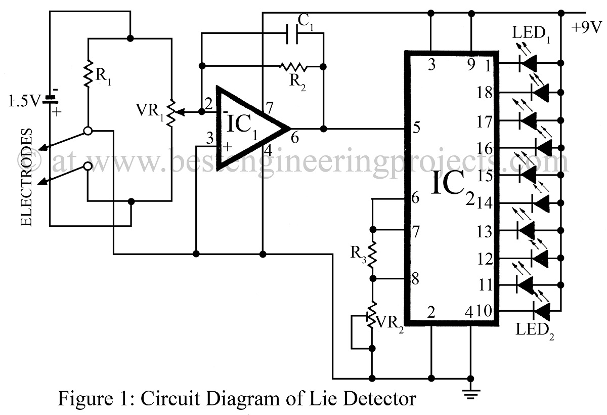
The lie detector presented here has been designed to detect skin resistance and provide a visual indication, verified electronic project. The lie detector circuit operates on the principle that skin resistance varies with emotional states, particularly during stress or deception....
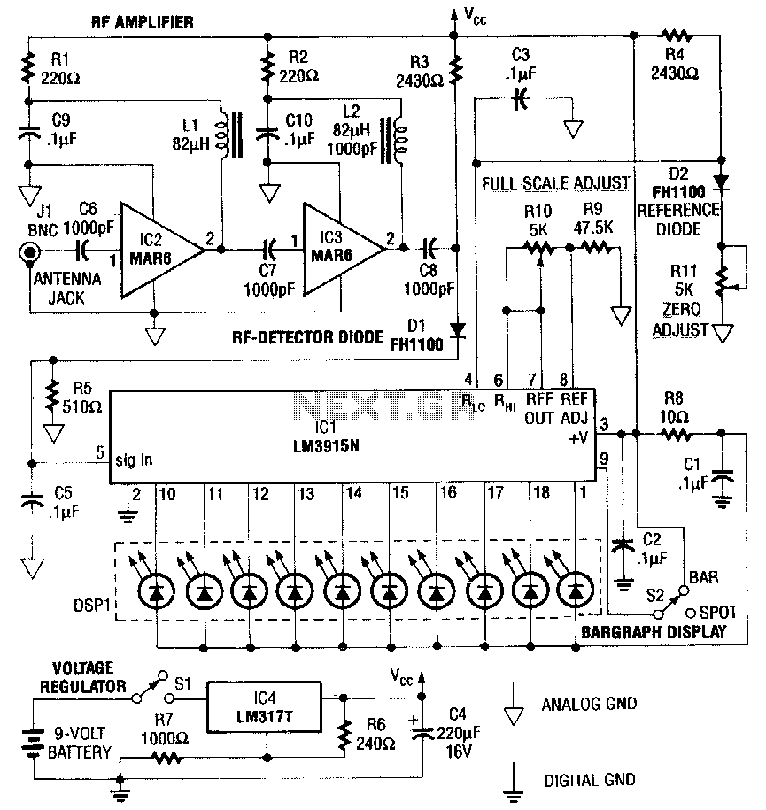
This RF detector is capable of locating low-power transmitters (such as bugs) that are not visible. It can detect the presence of a 1-mW transmitter from a distance of 20 feet, making it sensitive enough to identify even the...
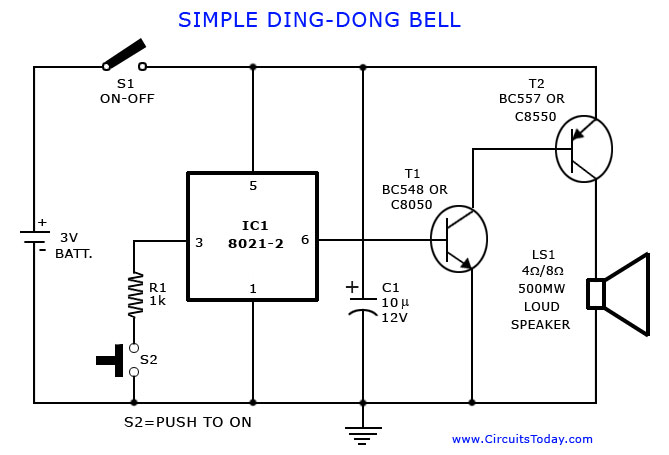
A tone generator circuit, which can be used to create a simple calling bell circuit, is illustrated here. It is constructed using the 8021 integrated circuit (IC), which includes built-in circuitry for producing a "ding-dong" sound. The tone generator circuit...
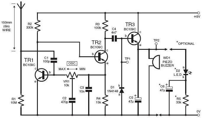
This DIY lightning detector circuit is a highly sensitive static electricity detector that provides an early warning of approaching storms from inter-cloud discharges well before an earth-to-sky return strike occurs. An aerial (antenna) made from a short length of...

The figure illustrates the circuit diagram of a multi-tone alarm, which fundamentally operates as an amplifier circuit. The core component of this circuit is the dual. The multi-tone alarm circuit is designed to produce various sound tones, enhancing its alerting...
A live-line detector is a circuit designed to identify the presence of a live mains conductor through capacitive coupling between the live conductor and the detection circuit. The live-line detector operates on the principle of capacitive coupling, which allows it...