
Tone generator with 555

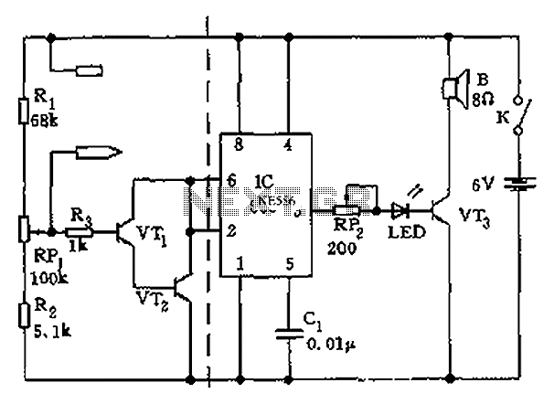
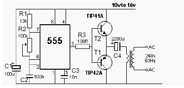
The described circuit utilizes the 555 timer IC in an astable configuration, which allows it to operate as a continuous oscillator. In this setup, the 555 timer generates a square wave output that can be used to create audio tones. The frequency of oscillation is determined by the values of two resistors and a capacitor connected to the timer.
In this specific design, one of the resistors is a potentiometer, which serves as a variable resistor, allowing for adjustable frequency control. By altering the resistance, the pitch of the generated tone can be modified, providing a simple means of sound modulation. The capacitor connected to the circuit plays a critical role in stabilizing the output by filtering out noise, ensuring that the adjustments made with the potentiometer result in smooth transitions in pitch rather than abrupt changes.
For practical applications, the circuit can be implemented with minimal components, making it cost-effective and easy to assemble. It is particularly suitable for projects requiring audio signals, such as alarms or sound effects. Additionally, the circuit can be adapted for Morse code applications by incorporating a switch at the output. This modification allows the user to manually control the tone generation, enabling the transmission of Morse code signals effectively.
Overall, this 555 timer-based oscillator circuit exemplifies a straightforward yet versatile design that can be employed in various electronic projects requiring sound generation.This circuit is based around the 555 timer circuit, used as an astable (free running) oscillator. The frequency (pitch) of the tone is set by the resistors and capacitors in the left side of the circuit. The first one is a potentiometer (variable resistor), this is our pitch control, which is basically all the external components you need.
The capacitor to the far left is to reduce as much noise or undesired operation of the potentiometer, getting a smooth pitch change when adjusting. Simple, low component count tone generator. It can be adapted to create a morse code circuit, by adding a switch to the output. 🔗 External reference
Related Circuits
The apparatus consists of a cavers point detection circuit and a triggering display circuit. The cavers instrument functions as a test probe, which, when held in one hand, can detect acupuncture points by touching the skin with another probe....

The project presented involves a verified circuit diagram for a two-tone doorbell that produces a "ding-dong" sound. It is part of a collection of various doorbell and alarm projects. The two-tone doorbell circuit typically utilizes a combination of capacitors, resistors,...

Generating sine waves with controlled frequencies over a wide range is challenging when using RC or LC sinusoidal oscillators. However, this can be effectively achieved using a wideband digital square wave oscillator, a counter, and a weighted summing network....
This 12V power inverter circuit can be utilized to supply power to small devices that require 240 volts. It is particularly beneficial when there is a need to operate equipment designed for 240 volts. The 12V power inverter circuit is...
This project displays telephone numbers decoded from tones. A microphone picks up the tones, a preamplifier boosts the signals, an SSI-202 DTMF chip decodes the tones, a Basic Stamp acts as an interface to an LCD display and also...

Circuit diagram for a DC power supply protection circuit. The device includes a buck rectifier power supply, a monostable delay circuit, a relay control circuit, and an audio feedback oscillation circuit. The entire circuit operates with a DC voltage...