
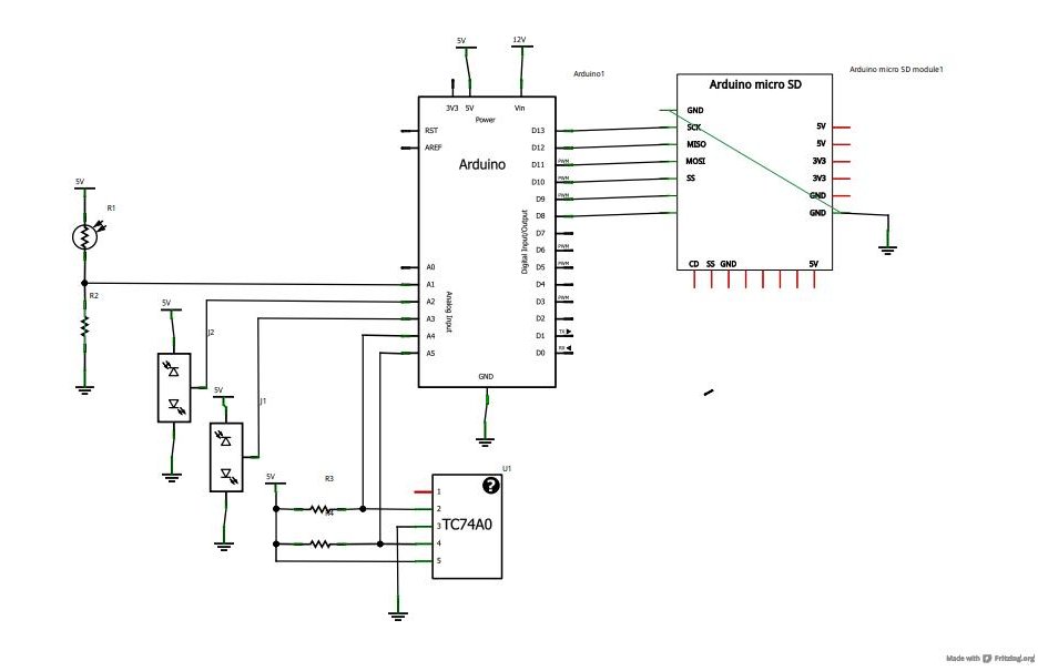
Touch Switch Data Input Interface
The interface circuit designed for digital data input utilizes a touch button as the primary input mechanism. When the touch button is activated, it sends a signal to the operational amplifier, which amplifies the input signal for further processing. The op-amp is configured in a non-inverting mode to ensure that the output signal is a clean, amplified version of the input.
The diode serves as a protection element, preventing reverse current that could potentially damage the circuit components. It ensures that the current flows in one direction, thereby safeguarding the op-amp and other sensitive components.
A capacitor is included in the circuit to filter out noise from the signal, providing a more stable output. It can also be used for debouncing the touch button, which eliminates false triggering caused by mechanical vibrations when the button is pressed or released.
Resistors are strategically placed within the circuit to set the gain of the op-amp, control the charging and discharging rates of the capacitor, and limit the current flowing through the diode. The values of these resistors can be adjusted based on the desired sensitivity and response time of the touch interface.
Overall, this interface circuit is versatile and can accommodate any conductive surface, making it suitable for various applications requiring digital data input through touch activation.This is an interface circuit for digital data input. This circuit consist of touch button, op-amp, diode, capacitor and resistors. Any conductor surface can be. 🔗 External reference
Related Circuits
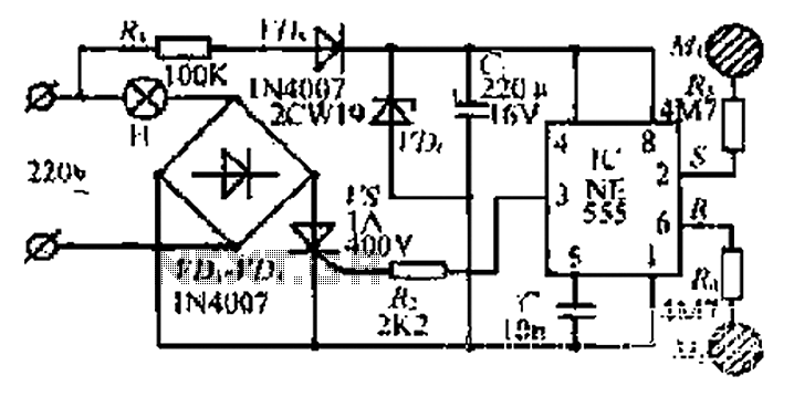
220V AC by Ri buck, Diao. C1 chain ferry flood ear, shouted for the regulator to 12V make C collapse. The film hand touch under ridicule the MT electrode films, clutter body. More: induction signal sent by See Cutting...
A reader named Andrea ([email protected]) submitted a circuit designed for educational purposes. The primary objective is to demonstrate how to electronically toggle an output state using only a push-button switch. According to Andrea, this simple circuit can drive a...
CMOS interface circuit with PMOS cross-coupled PMOS integrated circuit featuring high input impedance, where the input current can be ignored. The CMOS and PMOS interface circuit is illustrated in the accompanying figure. The CMOS interface circuit utilizing PMOS cross-coupled configurations...
Now that the basics have been covered in tutorials 1-10, it is time to pursue more complex projects. In this episode, an SD card shield from cooking-hacks.com will be utilized to create a data logger. The process of reading...
Touch operated switches are an attractive project for DIY electronics but they are not so common in commercial products. The reason for this is that, although there are many different ways of implementing a touch switch (leakage, hum pickup,...
As with the Electronic sel. 8 we also have here a circuit with a choice of 8 different sources. The difference is that only two of the switches are used and the movement of commands is Up-Down in series....
Warning: include(partials/cookie-banner.php): Failed to open stream: Permission denied in /var/www/html/nextgr/view-circuit.php on line 713
Warning: include(): Failed opening 'partials/cookie-banner.php' for inclusion (include_path='.:/usr/share/php') in /var/www/html/nextgr/view-circuit.php on line 713