
Touch SwitchCircuit Based On The CD4011 IC
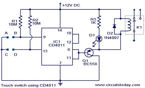
The Touch Switch Circuit utilizes the CD4011 integrated circuit, which consists of four NAND gates. In this configuration, the circuit is designed to detect a touch input and activate an output signal accordingly. The resistors R1 and R2 are crucial components that set the threshold for the touch sensitivity and help in defining the logic levels for the NAND gates.
When a user touches the designated area of the circuit, a small change in capacitance occurs, which is detected by the NAND gates. The output from the NAND gates can be connected to various loads, such as LEDs or relays, allowing the circuit to control different devices based on touch input. The circuit can be powered by a standard DC supply, typically ranging from 5V to 15V, depending on the specifications of the CD4011 IC.
To enhance the performance of the touch switch, additional components such as capacitors may be included to filter noise and stabilize the input signal. The design can be further optimized by adjusting the values of R1 and R2 to achieve the desired sensitivity and response time. Overall, this Touch Switch Circuit provides a simple yet effective solution for touch-sensitive applications, making it suitable for various electronic projects and devices.The following circuit shows about Touch Switch Circuit Diagram . This circuit based on the CD4011 IC. Features: R1 and R2, the logic gates of the .. 🔗 External reference
Related Circuits
This is an interface circuit for digital data input. The circuit consists of a touch button, an operational amplifier (op-amp), a diode, a capacitor, and resistors. Any conductive surface can be used. The interface circuit designed for digital data input...
The following circuit illustrates a Single Supply Phase Locked Loop Circuit Diagram. This circuit is based on the LM331 integrated circuit. Features include the response of... The Single Supply Phase Locked Loop (PLL) circuit utilizing the LM331 integrated circuit is...
The IQ_Demod project demonstrates the application of the IQ_Demod_Setup and IQ_Demod_Data components within the ADS environment. These components are included in the ADS behavioral model suite, located under the System - Data Models palette. The file "IQ_demod_ckt.dsn" represents the...
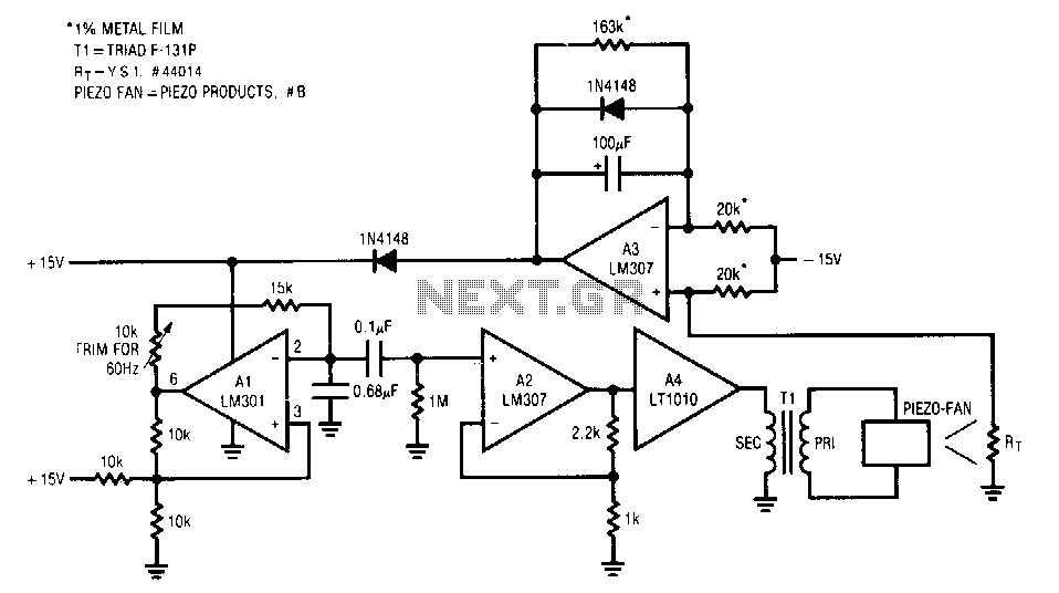
The fan used is a new electrostatic type, known for its reliability due to the absence of wearing parts. These devices require a high-voltage drive. When power is applied, the thermistor located in the fan's exhaust stream has a...
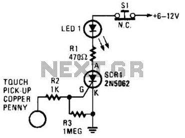
When the touch-on contacts are bridged, pin 6 of U1 goes low, which forces its output (the set output) at pin 4 to go high. That high divides along two paths; in one path, the output is applied to...
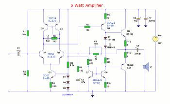
The diagram illustrates a 5W audio amplifier circuit constructed using power transistors BD139 and BD140 for the final amplification stage. This compact amplifier serves as a general-purpose amplifier suitable for applications such as computer audio, radio, MP3 players, and...