
Touch the socket circuit diagram
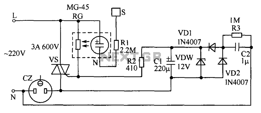
The circuit utilizes a TRIAC (VS) to control the AC load connected to the socket (CZ). The operation begins with the finger touch on the metal sheet (S), which causes the neon tube (N) to illuminate. This illumination decreases the resistance of the photoresistor (RG), allowing current to flow and trigger the TRIAC (VS). The TRIAC serves as a switch, controlling the power to the load based on the trigger current it receives.
The AC voltage from the power supply passes through bulk capacitors (C2) and diodes (VD1 and VD2), which rectify the AC signal into a DC voltage. This DC voltage is then regulated by a zener diode (VDW) to ensure a stable output voltage, which is essential for the reliable operation of the circuit. The filtered output is applied to resistor (R2) that is connected to the gate of TRIAC (VS), ensuring that the TRIAC remains in the conducting state even after the finger is removed from the metal sheet.
The circuit's design allows for a load capacity of up to 500W, making it suitable for various applications. The feature that prevents the socket from becoming live when no load is connected adds a layer of safety, ensuring that the circuit does not waste power or pose a risk when idle. The choice of components, including the MG-45 photoresistor and standard neon tube, reflects a balance between performance and availability, ensuring that the circuit operates effectively while remaining cost-efficient.
Overall, the circuit is efficient and user-friendly, providing a reliable means of controlling an electrical load through a simple touch interface while maintaining safety and energy efficiency. Circuit as shown, with a touch of a finger when the metal sheet S, N neon tube light, since N and photoresistor RG constitute optocouplers make RG resistance becomes smaller, s o the TRIAC VS because sufficient trigger current lead pass, it was electric socket load CZ on working. At the same time, 220V AC voltage through the CZ bulk capacitors C2, the diode VD1 and VD2 rectifier, regulator VDW regulator, filter capacitor C1 obtained by the DC voltage applied to the resistor R2 VS the gate, even if S has left finger touch, VS remains turned on, so that the load connected to the CZ normal power work.
When power is restored after power outage, because VS has not been enough to trigger current, it is not turned on, the load on the CZ is powered off. Only CZ retouches to make the load on the power. When not connected to the load circuit, the socket itself has little power (about 0.5W). Socket load capacity of up to 500W. The circuit also has a feature: when there is no load on the socket, even though the touch of S, the socket is not live.Component selection: Choose a neon tube N ordinary neon tubes, photoresistor RG choose MG-45 models.
VDW select regulator for the 12V zener diode. Resistor selection (1/4) Ws. Other components shown in FIG.
Related Circuits
Lamp dimmer. The circuit illustrated below can be employed for dimming lamps. It utilizes a minimal number of components, which can be conveniently installed within the lamp socket. This circuit is typically utilized in RC phase shift configurations. The...
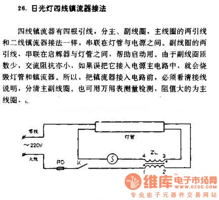
The four-wire ballast connection of a fluorescent lamp consists of four lead wires, which include main and auxiliary coils. The connection of the two lead wires in the main coil is similar to that of a second-line ballast; both...
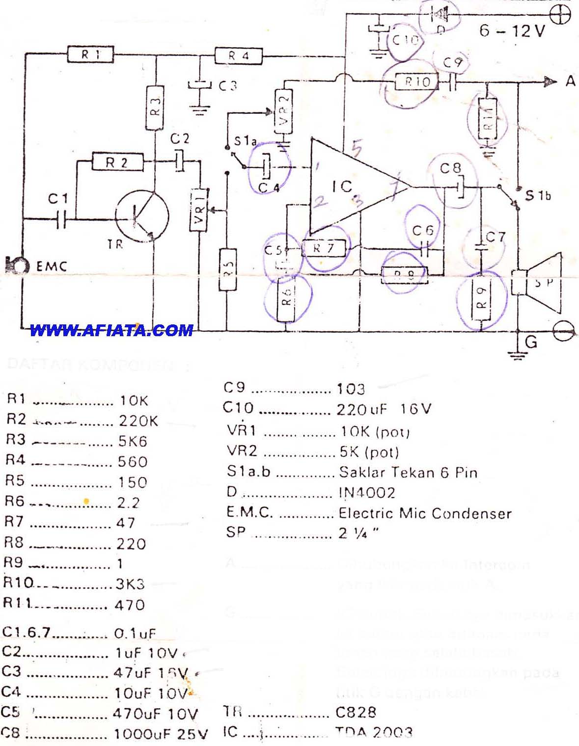
DIY Intercom Circuit Full-duplex intercom circuit schematic, cable on the way to the intercom circuit. The DIY intercom circuit is designed to facilitate two-way communication using a full-duplex system. This allows simultaneous transmission and reception of audio signals, enabling clear...
This circuit is designed to detect whether the load of a battery charger or plug-in adapter is properly connected. The load may consist of a set of batteries needing charging or any other device that operates on low DC...

The TBA120 Series integrated circuits (ICs) offer a high-gain limiting intermediate frequency (IF) amplifier and a quadrature coincidence detector in a single package. These ICs are primarily designed for the extraction of television intercarrier sound, which is frequency modulated...

AMP-04 is a single-supply, single resistor gain adjustment circuit with an input voltage drift of less than 150 pV, a current drift of 5 nA, and a temperature drift of 8 pA/°C. The gain nonlinearity is 0.005% of the...