
Traffic-light application in C language (AVR-007)
The project focuses on developing a traffic-light control system using the AVR-007 microcontroller. The AVR-007 is a versatile microcontroller that offers multiple input and output pins, allowing for efficient control of various components such as LEDs, sensors, and switches. A fundamental understanding of the microcontroller's architecture, including its pin configuration, memory allocation, and peripheral interfaces, is crucial for successful implementation.
The traffic-light application will involve programming the microcontroller to manage the timing and sequencing of the traffic lights. The typical traffic light consists of three colored LEDs: red, yellow, and green. Each LED will be connected to a designated output pin on the AVR-007. The microcontroller will be programmed to turn on each LED for a specified duration, simulating real-world traffic light behavior.
To begin, the hardware setup will require the following components: the AVR-007 microcontroller, three LEDs (red, yellow, and green), current-limiting resistors for the LEDs, a breadboard for prototyping, and jumper wires for connections. The LEDs should be connected to the output pins of the microcontroller with the appropriate resistors to prevent excessive current flow.
The programming aspect will involve writing code in a suitable language, such as C or assembly, that instructs the microcontroller to control the LEDs based on defined timing intervals. The code will include initialization routines, where the pins connected to the LEDs are configured as outputs. A loop will be created to cycle through the states of the LEDs, ensuring that the red light is displayed for a longer duration, followed by the yellow and green lights.
Testing the circuit will involve verifying the correct operation of each LED according to the programmed timing. Adjustments may be made to the timing intervals based on practical observations to achieve the desired traffic control functionality.
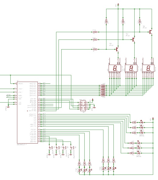
Overall, this project serves as an excellent introduction to microcontroller programming and hardware interfacing, providing hands-on experience in creating a functional traffic-light control system.learn to use microcontrollers to create traffic-light applications. In this project we will use microcontroller AVR-007 from Circuits-Home. Before creating the program, the first job we have to do is understand about the hardware specs. 🔗 External reference
Related Circuits
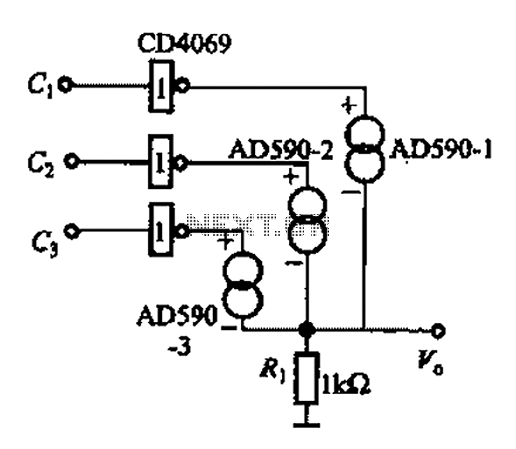
The AD590 is illustrated in a basic application circuit. As the AD590 provides a current output, a series resistance is used to convert this output current into a voltage. In the circuit, RP serves as the output voltage (vo)...

The applications outlined in this document pertain to driving high-power LED diodes. The circuits described can also be utilized in other applications with similar requirements, as long as they adhere to the specifications of the MLX10803. This is a...

The setup for the Square Wave Generator can be initiated using a 555 timer IC as illustrated in the accompanying circuit diagram. It is essential to reference the pinout configuration of the 555 timer IC. An oscilloscope should be...
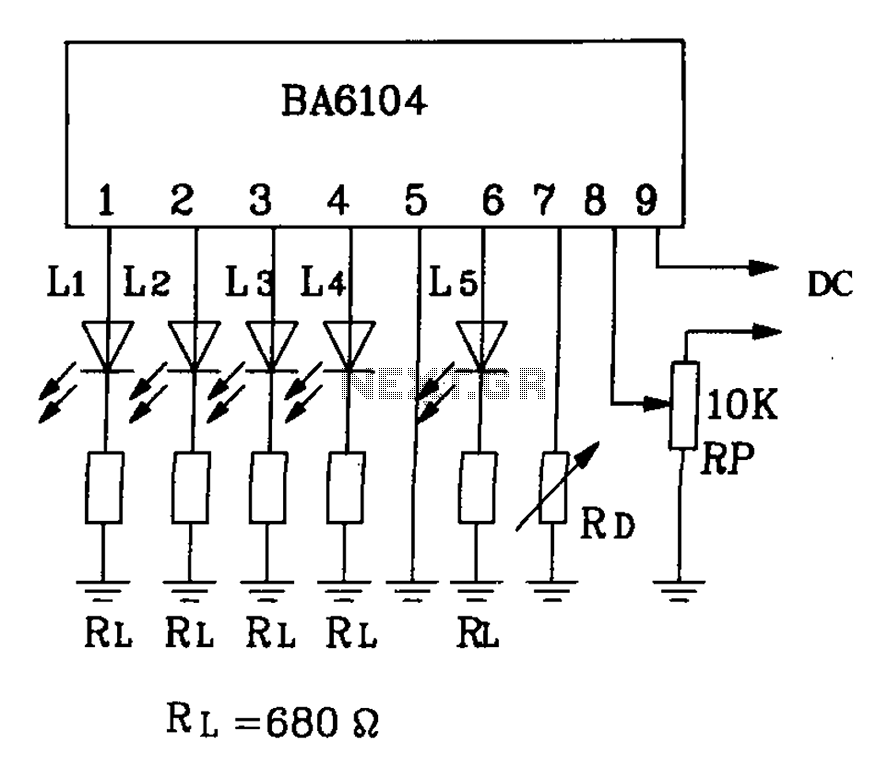
BA6104 is a five-digit LED level meter driver integrated circuit (IC) that features a basic application circuit. The input stage employs a PNP transistor with a composite base input, resulting in high input impedance. The output stage is configured...
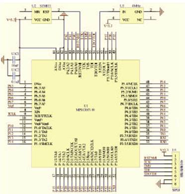
The target designator is designed based on the MSP430F149 microcontroller to facilitate rapid target identification in military training environments. It can adapt to various tactical requirements, allowing for the display of targets and the execution of bomb simulations according...

The YSS247 has several characteristics, including fewer external components compared to similar products. Unlike the SRS5250S, the YSS247 utilizes a single potentiometer to adjust the surround effect. The circuit allows for switching or turning the tone control to modify...