
Training Boxing timer schematic
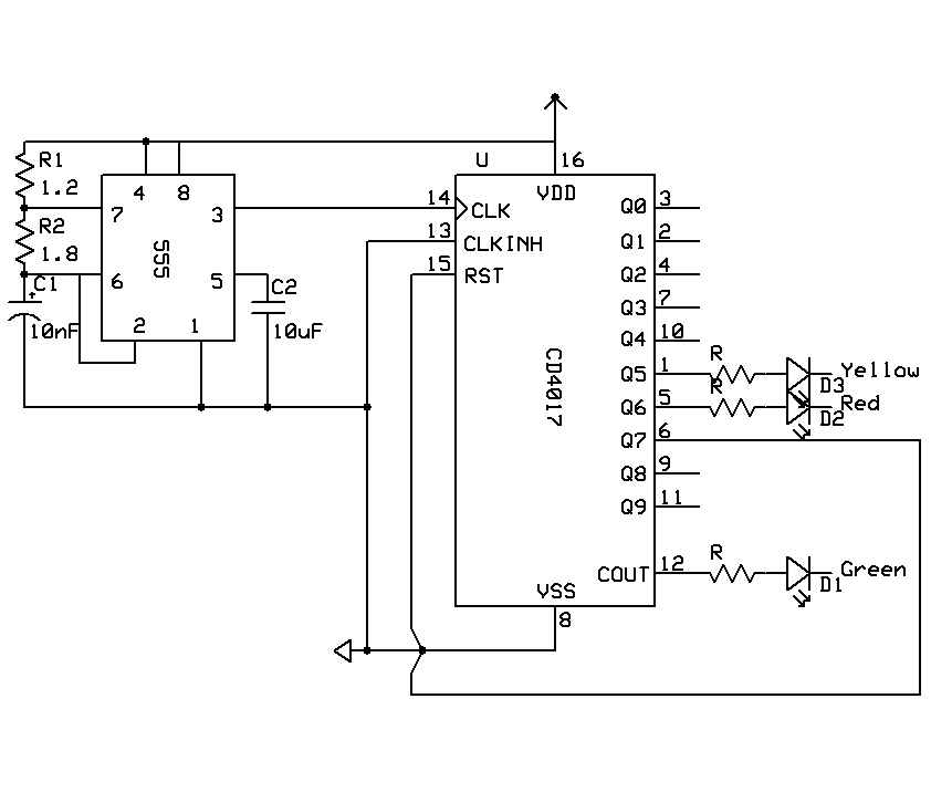
The circuit design involves several key components: a 555 timer configured in astable mode to generate a 30-second clock signal, which will drive a 4017 decade counter. The outputs of the 4017 will be connected to various indicators or actuators, with outputs 1 through 5 representing the first five intervals of the training session, while outputs 6 and 7 can be used for signaling the end of the cycle. The reset functionality ensures that after the completion of all intervals, the timer can be restarted without manual intervention.
The second part of the project incorporates a monostable 555 timer that activates a buzzer for a short duration. This timer is triggered by the output of the 4017, specifically when the lamp is lit, thus providing auditory feedback at the conclusion of each interval. The design must ensure that the monostable timer's output pulse duration is significantly shorter than the interval duration to prevent overlap and ensure clarity in signaling.
For the astable configuration of the 555 timer, the timing components—resistors R1, R2, and capacitor C1—must be calculated to achieve the desired 30-second period. Given the formula for the frequency of the 555 timer in astable mode, adjustments may be necessary to account for component tolerances. A variable resistor can be included in the circuit to allow for fine-tuning of the timing intervals.
When designing the monostable timer for the buzzer, it is crucial to ensure that the pulse width is appropriate for the intended feedback duration. The user must configure the resistor and capacitor values for the monostable circuit to achieve a 2-second output pulse, which can be verified using the appropriate timing formula for the 555 timer in monostable mode.
Overall, the circuit design combines both digital and analog elements to create a functional training timer, with careful consideration of timing accuracy, component selection, and feedback mechanisms to enhance the user experience during training sessions.Making a timer that is used for circuit training or boxing training etc. Here is the cycle I am looking for. This does not need any input, but to reset the timer to the beginning. its a simple project why not making it simpler by using a microcontroller you will not invest much take the pic12f635 for example, costs less than 2$ on top of that a few analog components that you are going buy anyways. You`ve got 7 equal intervals in total; use a 30-second 555 astable clocking a 4017, taking outputs 1-5, 6, 7, reset after the full cycle. For the short buzz, the 4017 output to the light switcher also (through steering diodes) starts a second 555 monostable connected to the buzzer.
The circuit needed is one which gives a short (timed) buzz even if the operating switch/button is held closed, so the start of the 30 seconds for which the lamp is lit sets it going for, say, only 1 second or less. That is what I thought. Thanks again. Here is the first attempt at the circuit without the buzzer. I used the divide by 10 for the first 5 counts to eliminate using diodes. Please be kind, this is first attempt. I am not EE I just play one on TV. Note: The schematic program i used could not jump over the connection at pin 8. Pin 6 and reset do not connect to pin 8. This is a crude attempt to jump over the connection. cpemma, you mentioned steering diodes. I think I know what you are talking about, but could I use the LED`s as steering diodes, or is the bias reversed How would they be connected cpemma, you mentioned steering diodes.
I think I know what you are talking about, but could I use the LED`s as steering diodes, or is the bias reversed How would they be connected On the Bill Bowden traffic lights circuit I linked, the 1N914 diodes are used to connect a block of 4017 outputs together so if any one of them is `high` that light is activated. Technically they`re OR gates so if Q0. OR. Q1. OR. Q2, etc are high the cathodes` junction point is high, but if Q0 is high there`s no short to the low Q1-Q4.
In your case Q0-Q4 would have diodes on each to a common point to give a 150s green, then Q5 alone (no diode needed) for 30s yellow, then Q6 alone for 30s red. Yes thank you. I have seen this circuit and a variation that help me greatly. I used cout instead of a bunch of diodes since I need exactly half the count thats where my confusion came in.
I will try to add the second 555 this afternoon and see how it works. I think I found a big problem with my math and the values for R1, R2 and C1. I want the 555 to pulse every 30 seconds. Either I am over thinking this or I have too few brain cells left to make the calculation For some reason I have the 555 running at 30Hz which is NOT 30 seconds. I found a great calculator at Doctronics that helps calculate the values for astable and monostable. Please help. At what frequency would I need the 555 running to equal 30 seconds. I am thinking. 3Hz 0. 03Hz. Another good calculator here. In theory, 47uF, 330k and 300k will be close, but due to the wide tolerance on capacitors a variable resistor (470k pot) will be needed instead of the 300k.
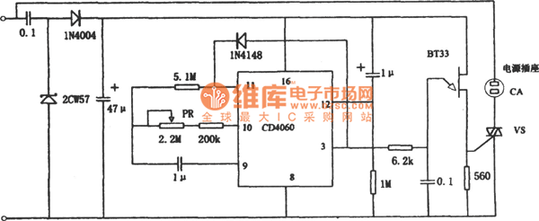
The `on` and `off` times don`t need to be equal. If you want the times to be accurate, a crystal-controlled timer and frequency-divider chain (eg, CMOS4060B) would be better and not much more complex or expensive. Even without a crystal, the 4060B would make a better clock as a low-value, more stable, film capacitor can be used.
See here. I was thinking and reading about the monostable circuit for the buzzer. I think I have a problem attaching it to the out of the 4017. Everything I have read says the the signal in must be shorter then the signal out. In this case I would have about 20 seconds ON time which would be too long. How can I connect the 555 to the 4017 The monostable circuit would be ON for about 2 seconds. 🔗 External reference
Related Circuits

The following method allows the timer to be triggered by a normally closed switch. This would be useful in applications such as intrusion alarms where the protection circuit is broken if a window or door is opened. Trigger Input...
The figure illustrates a preset outage timer circuit designed for an electric cooker. The timing range of the circuit extends from 1 hour to 12 hours, adjustable via a potentiometer (PR). The timing mode operates on a counting basis,...

This circuit is a compact timer designed to keep the headlights of a car illuminated for approximately 1.5 minutes before automatically turning them off. By integrating this circuit into a vehicle, users can access dark areas without the need...
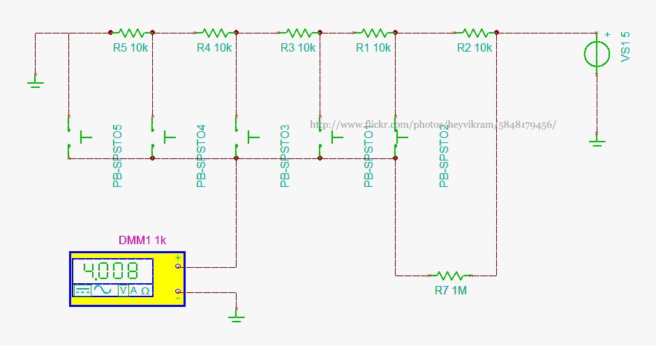
Connect a 5-way button/joystick to an Arduino using a single analog pin to quickly simulate it for verification of calculations before soldering. The voltages for the six states are 0, 1, 2, 3, 4, and 5. The 4V displayed...
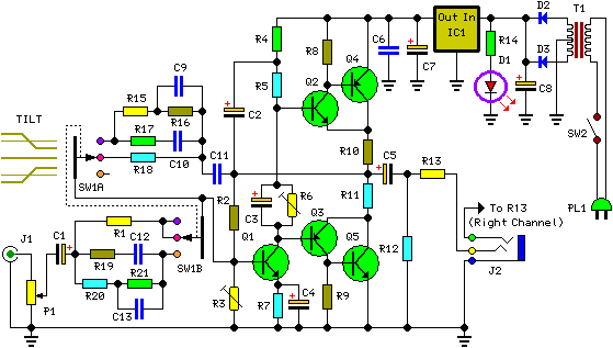
The described shunt-feedback configuration facilitates the straightforward incorporation of frequency-dependent networks, enabling a practical and unobtrusive switchable tilt control as an optional feature. When switch SW1 is in the first position, a gentle shelving bass boost and treble cut...
The 555 timer is commonly used in time-based circuit designs, particularly in monostable configurations. This setup is straightforward and requires only a few resistors and capacitors to achieve triggering. However, external interference can affect the operation of the circuit...