
Transistor Amplifier Circuit with Diagram for 12 Watts

This circuit is designed to amplify audio signals, making it suitable for applications such as driving speakers in a home audio system. The core component is a transistor, which operates in the active region to amplify the input signal. The circuit typically consists of a power supply, input coupling capacitors, biasing resistors, and feedback components that stabilize the gain.
The input audio signal is fed into the base of the transistor through a coupling capacitor, which blocks any DC component, allowing only the AC audio signal to pass. The transistor's collector is connected to the power supply, and the emitter is usually connected to ground through an emitter resistor, which helps in stabilizing the operating point and providing thermal stability.
An op-amp is utilized to achieve the desired gain. The op-amp configuration may be in a non-inverting or inverting mode, depending on the design requirements. Feedback resistors are employed to set the gain of the op-amp, ensuring that the output signal is an amplified version of the input. The output from the op-amp drives the base of the transistor, allowing for a significant increase in output power.
To ensure optimal performance, decoupling capacitors are placed near the power supply pins of the op-amp to filter out any noise. The output of the transistor can then be connected to a load, such as a speaker, where it delivers the amplified audio signal.
This 12-watt audio amplifier design is efficient and can be implemented on a printed circuit board (PCB) for compactness and reliability. Proper heat dissipation measures should be considered, as transistors can generate heat under load conditions. Overall, this circuit is a practical solution for audio amplification needs in various electronic projects.A simple transistor amplifier circuit diagram and schematic which can be used as a 12 watts audio transistor amplifier.An op amp IC is used to produce the gain required.. 🔗 External reference
Related Circuits
This circuit is a melody generator circuit diagram controlled by the UM66 IC. The UM66 is a CMOS IC designed for applications such as call bells, telephones, and toys. It features a built-in ROM programmed to play music and...
This transmitter can be utilized for multiple applications. An INS8048L microprocessor produces various codes based on keypad inputs. These codes are modulated onto a 40-kHz carrier frequency. Additionally, Q1 drives infrared LEDs LED1 and LED2. The transmitter circuit primarily consists...
The cooling is not only a PC using a small fan with an electronic commutator. A special feature of these fans is that their removal is less dependent on the load. Indicators monitoring the DC component of current may...
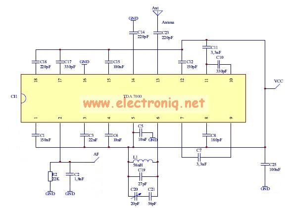
The TDA7000 features a Frequency-Locked-Loop (FLL) system with an intermediate frequency of 70 kHz, and selectivity is achieved through active RC filters. The only calibration required is for the resonant circuit associated with the oscillator, which is necessary for...
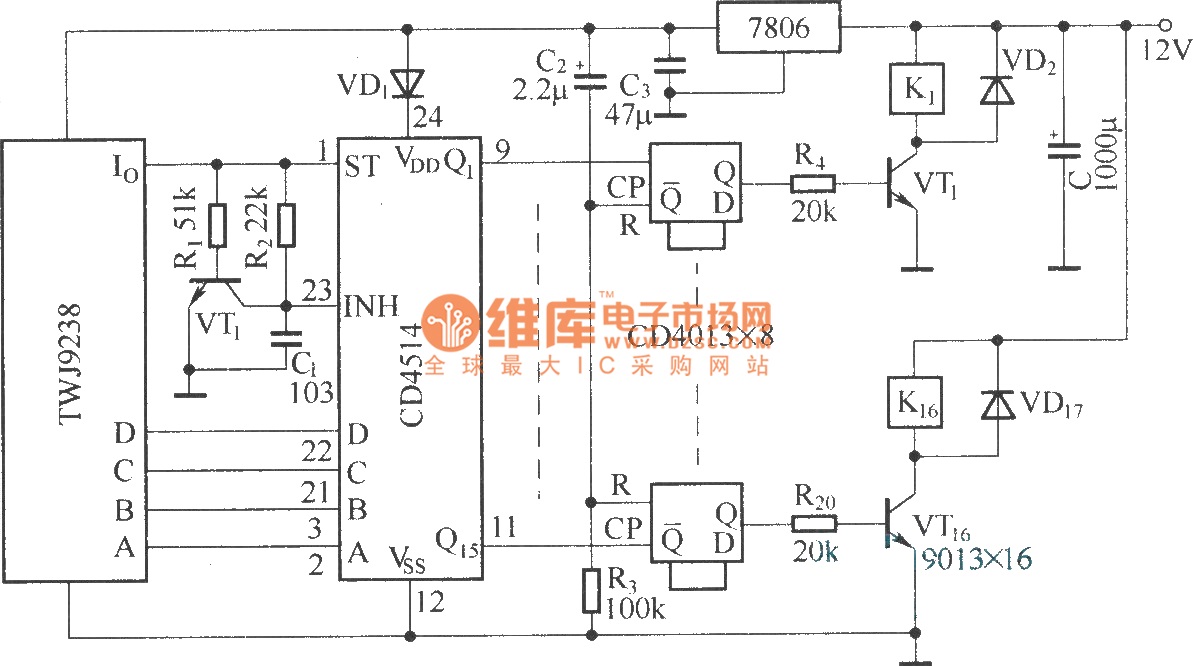
The Sixteenth Street control circuit consists of a secondary decoding output control circuit. Each output terminal of the sixteen decoding is connected to a bistable circuit made up of dual D flip-flops (CD4013). A DC relay is connected to...
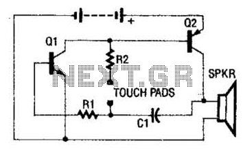
The circuit employs a two-transistor direct-coupled oscillator, with its frequency determined by capacitor C1, resistor R2, and the skin resistance across the touch pads. Since C1 and R2 are fixed values, only the skin resistance can vary the sound...