
transistor ignition shematic 3
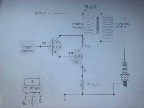
A transistor ignition system serves as an efficient alternative to traditional point breakers in motorcycle ignition systems. The proposed circuit typically consists of a Hall Effect sensor, which detects the magnetic field produced by a rotating magnet attached to the engine's flywheel. This sensor generates a pulse signal that triggers a power transistor, such as a PNP transistor in a TO220 package, which subsequently controls the ignition coil.
The Hall Effect sensor, such as the Honeywell SS466A, operates by producing a voltage output when exposed to a magnetic field. The output from the sensor is connected to the base of the PNP transistor, allowing it to switch on and off based on the sensor's output. When the transistor is activated, it completes the circuit for the ignition coil, allowing current to flow and generating a spark at the spark plug.
In addition to the Hall Effect sensor and the PNP transistor, the circuit will include diodes for flyback protection, which safeguard the transistor from voltage spikes generated by the ignition coil when it is turned off. Resistors may also be included to limit current and ensure the proper operation of the circuit.
For the schematic, the input signal from the Hall Effect sensor should be connected to the base of the PNP transistor. The collector of the transistor is connected to the positive terminal of the ignition coil, while the emitter is connected to ground. The polarity of the connections is crucial; thus, it is important to ensure that the positive side of the power supply is connected to the appropriate terminals of the ignition coil and the transistor collector.
In summary, the design of a transistor ignition system involves careful consideration of component selection, circuit configuration, and input/output connections to ensure reliable operation. Proper documentation and clear labeling of circuit diagrams are essential for effective implementation and troubleshooting.Hello All Experts, i m in need of Transistor Ignition to replace point breaker from my motorcycle. i read many many articles in internet google and almost all forums but did not yet found working and simples smallest circuit yet. and which i found they dont have answers about parts of any other related question and most of thm copid and old and pa
rts hardly available in market. The small transistor like packages are probably the Hall Effect sensors from someone like Honeywell (SS466A ). It looks like these are used to pick up the magnetic field of a rotating magnet (that cylindrical silver thing) and are used to drive the big TO220 transistors (cannot see the part number).
The other packages are diodes and resistors. Unfortunately I cannot give you any more circuit detail than that Somewhere out in "internetland" there is a simple circuit for a transistorized ignition that used one PNP power transistor. It still used breaker points, but it would be very simple to adapt the base input to work with a Hall sensor or the like.
I`m sorry I never saved the web address, but its out there. If I could find it, anyone can. I bought all of the parts to build it along with a small box to house it. I sold the bike and moved and I don`t know if I saved any of that stuff or not. If I can find it you can have it for a very low price. Dear Debe, Thanks for your post, it is really informative and wonderful. i have few question regarding this schematic aas i m dumb at electronics. i will use pulse trigger for triggering. where to connect the input of signal the schematic you attached has no input point for signal also need which point is Negative side and what is positive side of wires/connections. 🔗 External reference
Related Circuits

At the core of the CD4-MX is an astable multivibrator, constructed using transistors Q1 and Q2, which drives step-up transformer T1. The output from T1 is rectified by diodes D3 to D6 and utilized to charge capacitor C4. Upon...

The circuit consists of a delay loop, discriminators, output circuits, power supply, and indicator lights, divided into five parts. The power regulation is achieved through a resistor (R), while the power regulator is constructed using a voltage source. In...
This is a one-transistor LED flasher circuit designed to flash a super bright LED. The circuit employs a single transistor as a driver, which receives the flash rate from LED 2, a self-flashing LED. The flash rate can be...

An AC-DC power supply without a power switching circuit is typically employed in lighting load circuits. When the power grid is restored, the standby power supply automatically switches on. The automatic switching circuit utilizes a transistor, as illustrated. The...
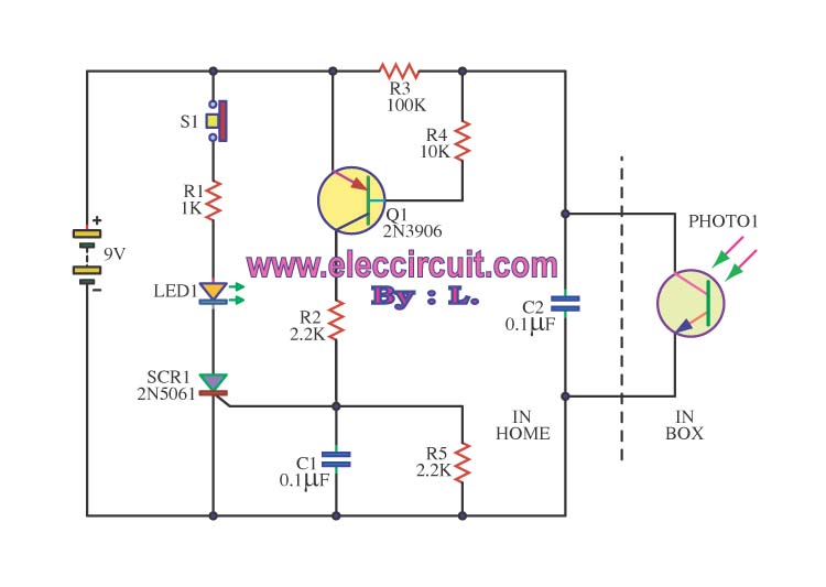
This is an integrated electronic mailbox circuit diagram designed for a front door. It activates when the door is opened. Additionally, when the cabinet photo detector is exposed to light, it will... The integrated electronic mailbox circuit is designed to...

This circuit is designed to provide an affordable method for creating a high impedance voltmeter using a low-cost analog or digital multimeter. The circuit is specifically intended for testing phototransistors. When measuring voltages in high resistance circuits, the resistance...
Warning: include(partials/cookie-banner.php): Failed to open stream: Permission denied in /var/www/html/nextgr/view-circuit.php on line 713
Warning: include(): Failed opening 'partials/cookie-banner.php' for inclusion (include_path='.:/usr/share/php') in /var/www/html/nextgr/view-circuit.php on line 713