
Transistor intercom circuit
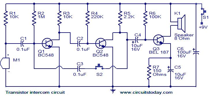
The intercom circuit utilizes a configuration of transistors to achieve both signal generation and amplification, making it suitable for simple communication needs. The three-stage RC coupled amplifier design enhances the gain while maintaining signal integrity. The astable multivibrator mode, activated by pressing the pushbutton, generates a square wave signal that serves as a ringing tone, alerting the user on the other end.
Transistors T1 and T2 are configured to form the oscillator part of the circuit, with capacitors and resistors determining the frequency of oscillation. When the pushbutton S2 is pressed, the circuit oscillates, producing a ringing signal that is then fed into transistor T3. This transistor acts as a power amplifier, boosting the signal sufficiently to drive the speaker, ensuring that the ringing is audible.
Once the pushbutton is released, the circuit transitions back to its amplifier mode, allowing for clear audio communication. The design ensures that the intercom system remains efficient, with a standby current of around 20 mA, which is relatively low and ideal for continuous operation without excessive power consumption.
For a two-way intercom setup, it is essential to construct two identical circuits. Each circuit should be connected according to the specified connection diagram, ensuring that both can operate independently while still being capable of communicating with one another. This configuration allows for effective two-way communication, making it suitable for various applications, including home intercom systems, office communication, and other scenarios where simple, reliable audio communication is required.Here is a simple but effective intercom circuit that is based fully on transistors. The circuit is based on a three stage RC coupled amplifier. When the pushbutton S2 is pressed, the amplifier circuit wired around T1 & T2 becomes an astable multivibrator and starts producing the ringing signals. These ringing signals will be amplified by the transi stor T3 to drive the speaker. When the push button S2 is released the circuit will behave as an ordinary amplifier and you can talk to the other side through it. To construct a two way intercom, make two identical copies of the circuit given below and connect it according to the given connection diagram.
The stand by current consumption of this circuit is around 20mA. 🔗 External reference
Related Circuits

This circuit is designed to detect the approximate percentage of salt contained in a liquid. After careful calibration, it provides a quick, rough indication of the salt content in liquid foods for dietary purposes. The circuit utilizes the LM324...
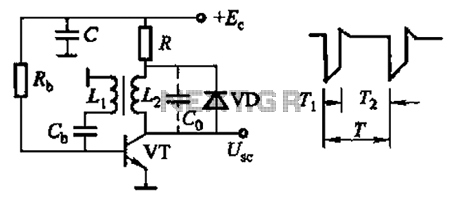
Common non-sinusoidal oscillator circuit, waveform and frequency formula - sawtooth oscillator - use blocking oscillator The sawtooth oscillator is a type of non-sinusoidal oscillator that generates a waveform characterized by a linear rise in voltage followed by a rapid drop....
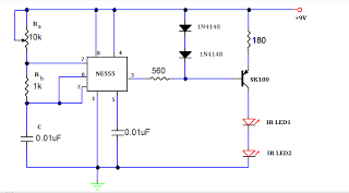
A TV remote jammer circuit using the NE555 timer IC. This device allows users to watch their favorite TV channels without interruptions, as it prevents others from changing the channel using a remote control when the circuit is activated....

The I2C PIC Interfacing Tutorial circuit is relatively straightforward; however, it requires careful verification to ensure that all connections are correct before initial operation. The primary components utilized in this circuit include the PIC18F452 microcontroller, the 24LC02B EEPROM, and...
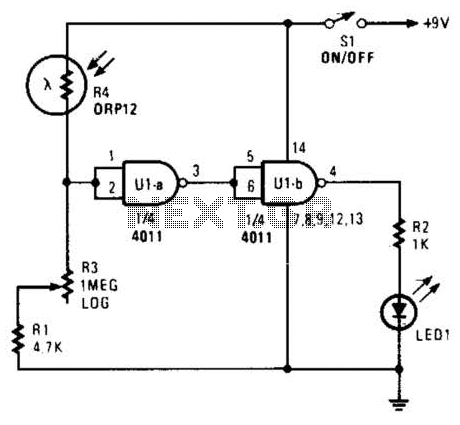
Two gates of a 4011 IC are utilized as a comparator. When the resistance of R4 decreases, the voltage at pins 1 and 2 increases, resulting in a logic zero at pin 3. This causes pin 4 to go...
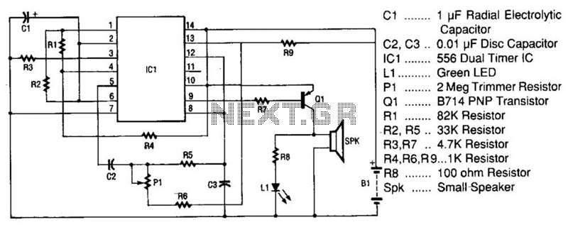
The space-age sound device utilizes a 556 dual timer integrated circuit (IC) to generate a phasor sound. This IC consists of two 555 timer circuits within a single 14-pin package, as depicted in the schematic. Each timer operates in...