
Transistor Tester Identifies Terminals Power

The simple transistor tester circuit is designed to facilitate the identification of transistor types (NPN or PNP) and to verify the functionality of the transistor's terminals: emitter, collector, and base. The circuit typically consists of a few key components, including resistors, a power supply, and a transistor socket for easy insertion of the device under test.
When the transistor is inserted into the socket, the circuit applies a small voltage to the base terminal, which allows for the determination of the transistor type based on its response. For an NPN transistor, a current will flow from the collector to the emitter when a positive voltage is applied to the base. Conversely, for a PNP transistor, the current will flow from the emitter to the collector when a negative voltage is applied to the base.
The circuit may also include an LED indicator that lights up when the transistor is functioning correctly, providing a visual confirmation of the transistor's operational status. Additionally, the use of multimeter probes can enhance testing capabilities, allowing for the measurement of voltage and current levels across the transistor terminals.
This simple tester is an invaluable tool for electronics enthusiasts and professionals alike, as it provides a quick and effective means to assess transistor functionality without the need for complex equipment. Proper understanding and usage of this circuit can lead to more efficient troubleshooting and repair of electronic devices.The simple transistor tester in Figure 1 lets you identify the type of transistor, and it helps in detecting a transistor`s emitter, collector, and base.. 🔗 External reference
Related Circuits
The single-junction transistor is commonly utilized in sawtooth and pulse generators, and it can also be configured to create a basic sine wave generation circuit. As an oscillator circuit composed of discrete components, it requires a minimal number of...

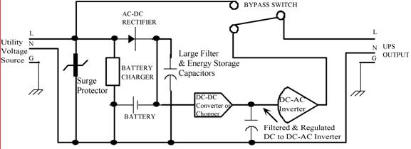
Traditional UPS systems use analog circuit control, which presents significant limitations for both manufacturers and users, regardless of whether they employ technology or SPWM technology. With advancements in information technology, the introduction of high-speed digital signal processing chips, known...
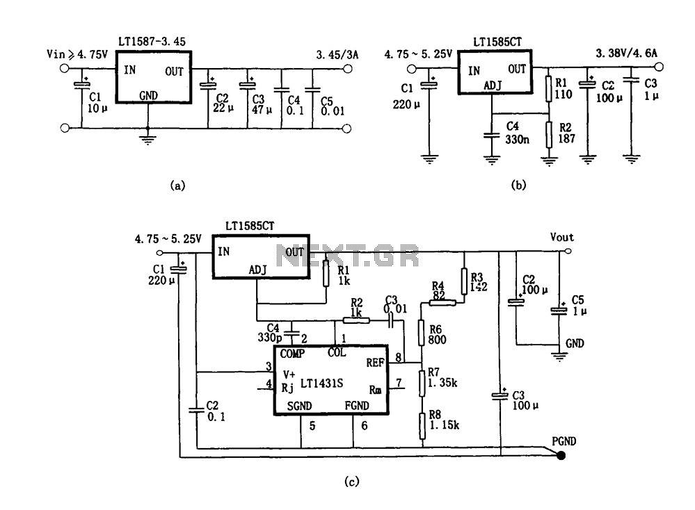
Figure (a) illustrates a microprocessor power supply circuit utilizing the LT1587-3.45. Figure (b) depicts a power supply with an adjustable output voltage constructed using the LT1585. Figure (c) showcases a computer power supply circuit formed with the LT1584 and...
Thomas Edison developed the incandescent light bulb, which operated from a 110-volt DC source. The primary drawback of DC power was that it could only be distributed over short distances without needing to be regenerated. In the early 1900s,...

The circuit includes a current limiting feature that is more reliable than most commercial units. It employs three pass transistors that require heat sinks. Resistor R9 allows for fine-tuning of the output voltage to precisely 13.8 volts, while the...

An additional push-button switch is typically required for the ATX Power Switch/Soft Power Switch signal; however, this simple circuit eliminates that need. The design is effective and has undergone extensive testing. A zener diode is included to protect against...
Warning: include(partials/cookie-banner.php): Failed to open stream: Permission denied in /var/www/html/nextgr/view-circuit.php on line 713
Warning: include(): Failed opening 'partials/cookie-banner.php' for inclusion (include_path='.:/usr/share/php') in /var/www/html/nextgr/view-circuit.php on line 713