
TRIAC Basic Operation
The TRIAC is a semiconductor device that enables the control of alternating current by allowing current to flow in both the positive and negative cycles of the AC waveform. It is essentially a bidirectional thyristor that can be triggered into conduction by a gate signal. Once triggered, the TRIAC remains in the conducting state until the current flowing through it drops below a certain threshold, known as the holding current.
In typical applications, TRIACs are used in light dimmers, motor speed controls, and heating control systems. The ability to control power in both directions makes them particularly useful for managing AC loads.
The operation of a TRIAC can be understood through its three terminals: the anode (A1), the anode (A2), and the gate (G). When a small voltage is applied to the gate, the TRIAC becomes conductive, allowing current to flow between A1 and A2. The device can handle high voltages and currents, making it suitable for various power control applications.
In terms of circuit design, the TRIAC can be integrated with additional components such as resistors, capacitors, and optoisolators to create more complex control systems. For instance, using an optoisolator in conjunction with a TRIAC allows for electrical isolation between the control signal and the AC load, enhancing safety and reliability in the circuit.
When designing circuits that utilize TRIACs, it is essential to consider parameters such as the maximum voltage rating, current rating, and the required gate trigger current to ensure proper operation and prevent damage to the component.Triode for alternating current,TRIAC, is an electronic component that can control power in two direction in an AC circuit. The figure (a) shows the block. 🔗 External reference
Related Circuits
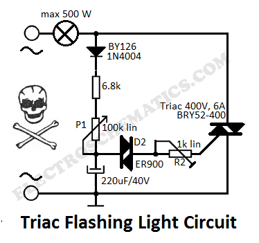
This flashing light circuit utilizes triacs to produce an intermittent light with variable frequency. Additional components include the D1 diode and a semi-adjustable resistor. The flashing light circuit is designed to create a visual indication through intermittent illumination, which can...
The series of light switches is slightly different from traditional designs. These light switches can operate directly on the AC power network. The main components of the circuit include a TRIAC and a Light Dependent Resistor (LDR). The circuit...
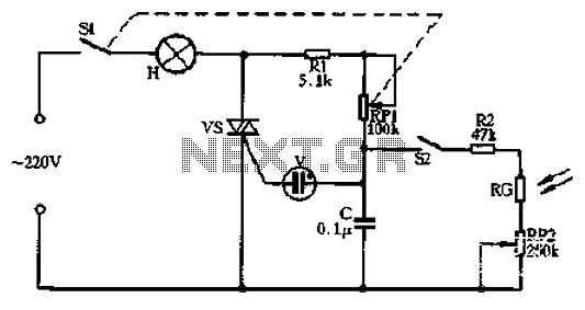
Circle S2 is a stable automatic light switch. When S2 is open, the entire circuit operates as a subsection II SCR stepless presentation dimmer, omitting the high-frequency filter circuit. The trigger diode switch activates a neon indicator bulb (V),...
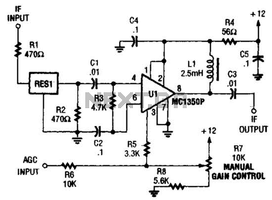
The ZN416E can be configured as a simple 455-kHz IF amplifier. In this case, the circuit's center and bandwidth are set by RES1 (a Murata CSB455E ceramic resonator). The ZN416E is a versatile integrated circuit designed for use as a...
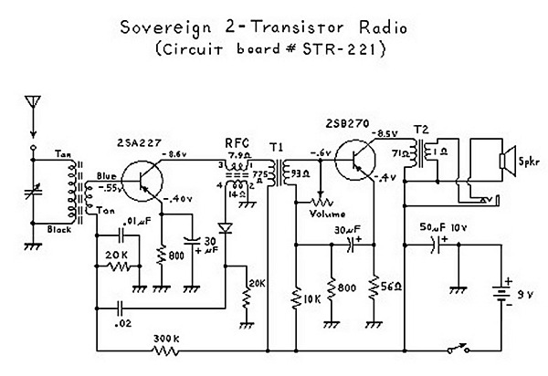
An analysis of certain radios reveals the impressive engineering by Japanese designers, particularly in creating a radio capable of driving a speaker with only two transistors. The first transistor (Q1) serves a dual function; it operates as an RF...
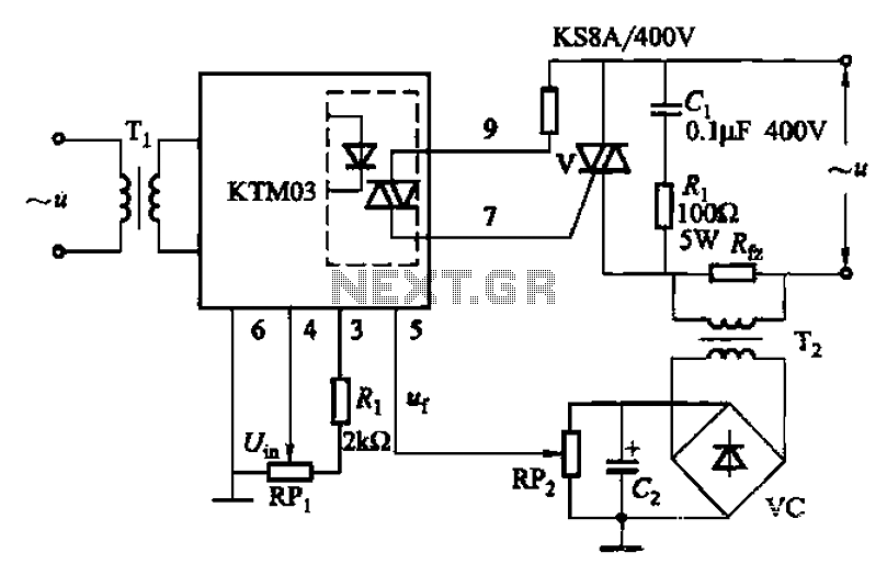
An adjustment potentiometer (RP) is utilized to set the voltage across the load resistor (Rfz) to a predetermined value. The real-time closed-loop control is achieved through the potentiometer (RPz). Open-loop control is functional as long as the feedback voltage...
Warning: include(partials/cookie-banner.php): Failed to open stream: Permission denied in /var/www/html/nextgr/view-circuit.php on line 713
Warning: include(): Failed opening 'partials/cookie-banner.php' for inclusion (include_path='.:/usr/share/php') in /var/www/html/nextgr/view-circuit.php on line 713